Gendered Connectors in Electronics

Using the male/female terminology for connectors seems to be the industry standard. In the past I have never questioned this. Its just how things are and how I learned to work with them.
In one of my recent KiCad-Workshops I talked to people that would like to get rid of those words. There are a few issues with using the sex-analogy:

  • Its not always clear what exactly is male. Quite a few connectors that are “inserted” are considered female. There are also female connectors that have protruding pins[1].
  • The language is non inclusive
  • Not all vendors use the same terminology

There has been some movement in the industry to address this problem. One example is the PAMA Recommendations for Neutral Nomenclature in Pro Audio from the Professional Audio Manufacturers Alliance (PAMA).

The proposed solution is to replace male/female with plug/socket, or pin/receptacle depending on the actual connector.
This is quite clever, since it solve the ambiguity of male what means: ‘will be inserted’ vs. ‘does have pins’.

There is no good reason why we, as an open-source community, should not improve our naming. On the contrary, we are not bound by weird corporate rules, but have the ability and freedom to be a leader of change. Both in the technical and inclusion aspect.

So lets do some research next, to see if and how we can untangle this Goardian knot.

D-Subminiature connectors

There are way to many different connectors out there to research them all. So I decided to start with the D-Sub type since they are well known and lots of manufacturers make them. Also there are standard documents describing them.

Vendors

When looking at how vendors name their connectors, there is not a single truth[2].


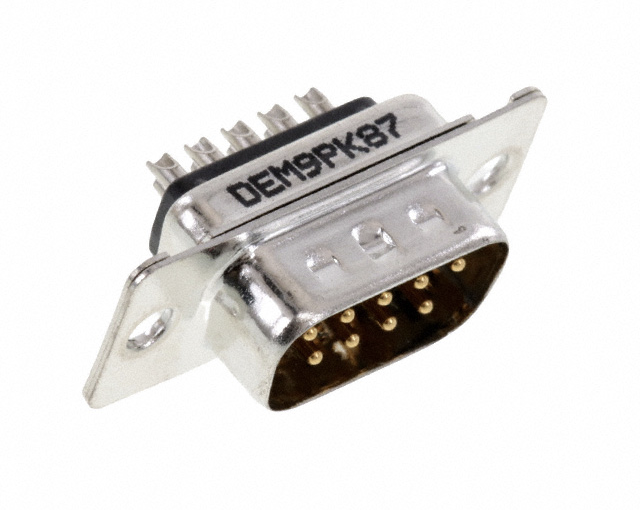
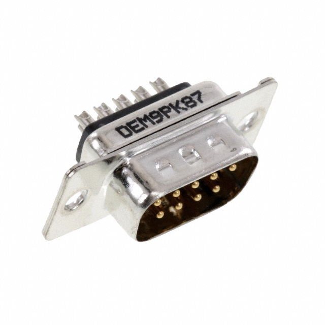
A “male”[3] D-Subminiature DE-9[4] connector. It has a shroud (the metal shell surrounding the pins). One can argue that the counterpart gets inserted into this connector. So this should be female?
We will learn later that at least for this type of connector, male == pins. Which is a good argument to just call it pins since its less ambiguous.

VendorPart numberNamingLink
Amphenol ICCD/8656/ DP SERIESPin/Sockethttps://www.amphenol-cs.com/media/wysiwyg/files/documentation/datasheet/inputoutput/io_dsub_d8656.pdf
Tyco Electronic1-5747150-3Receptaclehttps://www.te.com/usa-en/product-1-5747150-3.html
Würth210111003Malehttps://www.we-online.com/katalog/datasheet/210111003.pdf
Canon ITTDE-9P-K87Pinhttps://media.digikey.com/pdf/Data Sheets/ITT PDFs/DE-9P-K87.pdf
JAEDE-9SF-NPin/Sockethttps://www.jae.com/direct/topics/topics_file_download/?topics_id=66362&ext_no=06&index=0&_lang=en
Assmann WSWA-DF 09 LL/ZMale/Femalehttp://www.assmann-wsw.com/uploads/datasheets/ASS_4884_CO.pdf
NorComp171-009-103L001Male/Femalehttps://content.norcomp.net/rohspdfs/Connectors/17Y/171/171-YYY-10YLYY1.pdf
3M8200 & 8300 SeriesPlug/Receptacle/Sockethttps://www.3m.com/3M/en_US/p/c/electronics-components/interconnect-products/input-output-connectors/d-shaped/
Molex1727040160Malehttps://www.molex.com/webdocs/datasheets/pdf/en-us/1727040160_DSUB_PRODUCTS.pdf

There are at least 20 different vendors for DE-9 connectors on Digikey, I did not check all of them. That is not needed, it is quite obvious that vendors don’t agree on naming.

Other PCB tools

Orcad® Layout

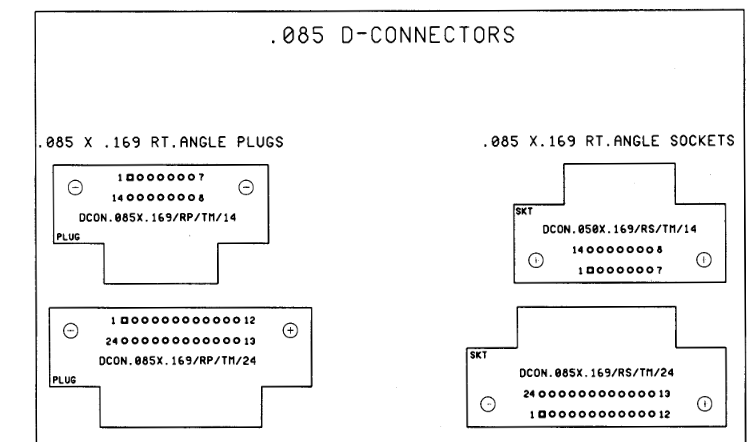
Uses Plug & Socket

Source: http://ohm.bu.edu/~pbohn/__Engineering_Reference/pcb_layout/Footprints.pdf

Target 3001!

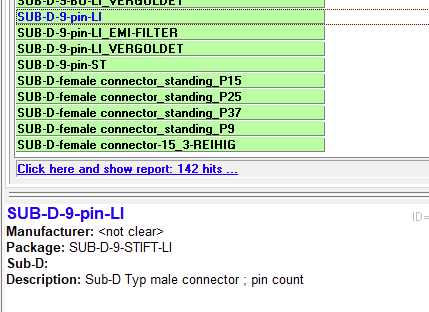
Uses STIFT (=pin) and male at the same time.

Altium Designer

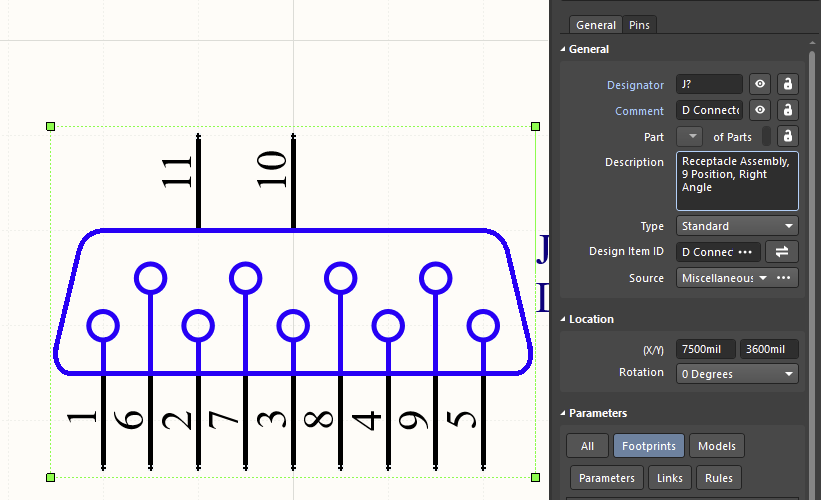
Uses Receptacle

Standard documents

Okay, next up we take a closer look at the standard documents. There are quite a few different standards to consider.

German DIN 41652 (D-Sub connectors)

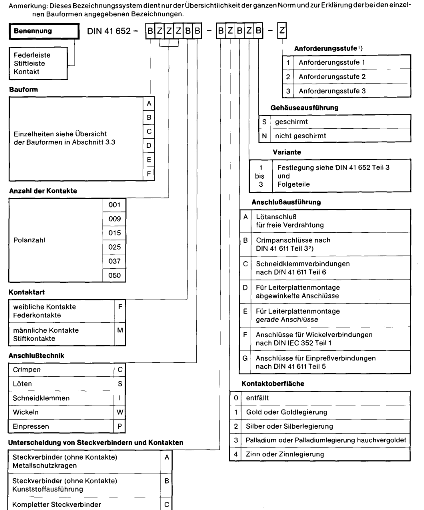
The German DIN uses

  • F = female contacts – spring contacts
  • M = male contacts – pins

The interesting part here is that the proper letter would be W (weiblich) instead of F to indicate the gender. One could argue that the F stands for Federkontakte. Most likely, this is just a translation issue (as in the letters are not translated at all). I guess the letters (m/f) are supposed to indicate gender.
What is clear here, the male/female wording aims at the pins, not the connector shell.

International IEC 60807-2

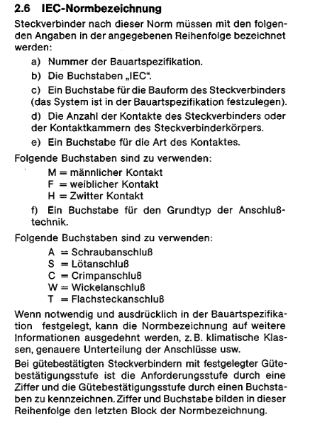
Unfortunately I only have the German translation of this. Its pretty similar to the the same as DIN 41652:

MIL-C-24308C

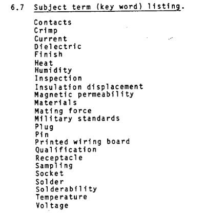
I could not find the words male or female in there at all. The document always refers to “plugs and receptacles”. The key word listing has pin/socket and plug/receptacle.

Data for other connectors

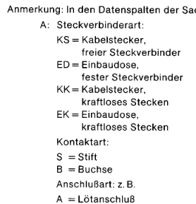
DIN 4000-54 “Sachmerkmal-Leisten”

This norm has rules that specify how different connectors should be described.
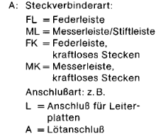
The tables that describe the contact don’t mention male/female. Instead Messer/Feder (translated to Socket/Pin) is used.

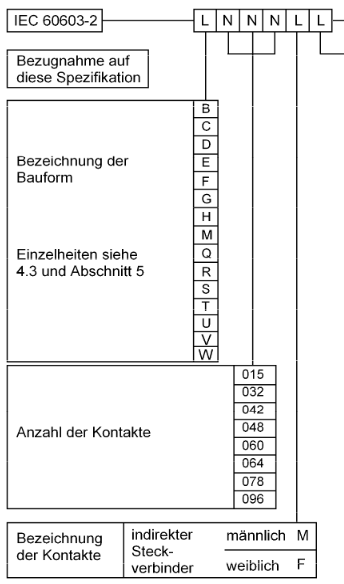
DIN EN 60603-2 (Replaces DIN41612)

Those are connectors used in rack systems. See https://en.wikipedia.org/wiki/DIN_41612 for some pictures.
The connectors of this series are named male/female in the spec.

Interestingly enough, TE calls them Plug/Receptacle.

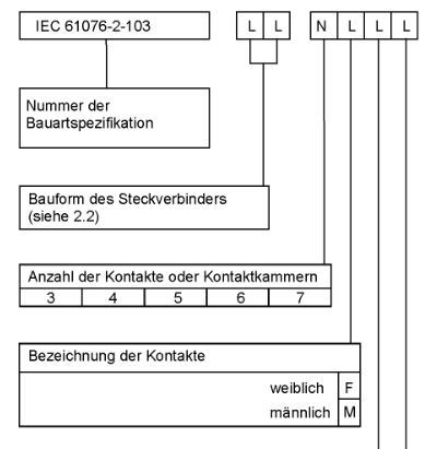
XLR (EN 61076-2-103:2004)

The connectors of this series are named male/female in the spec.
As far as I can tell, vendors (Neutrik, Switchcraft) also choose this naming scheme.

So what does ‘inclusive language’ actually mean?

That is hard, perhaps impossible for me to answer. I have always been included in a tech environment. As a member of the dominant culture I don’t experience microagressions when reading those words.
Other people however are affected by this language. Those asked me to do something about it. I want KiCad to be a safe space for anybody. That’s my main motivation to change things.
Given how small the cost of a change is, I am much in favor of getting rid of non-inclusive words.

Conclusion

We learned that there is no single truth, thus we need to weight our options.
Regarding the KiCad-Library I made the following decisions:

  • D-Subminiature rename to Pin/Socket.
    • Solves the confusion about what is considered male
    • About half of the vendors use that naming
  • XLR and DIN EN 60603-2
    • Stick with male/female
    • Its consistent with vendor naming and standards
    • Its still ambiguous 🙁
  • Connector_Generic
    • They are generic, with no footprint and thus not vendor associated
    • The names are made up, so we can just change them as we like
    • Pin/Socket seems like a good fit
  • RJ45 Jacks (I did not explicitly research them)
    • everybody already calls them jacks
    • Just rename them to jack or socket
  • USB Connectors
    • They don’t have protruding pins
    • The spec does specify what a jack and plug is

I get that people will be unhappy with this change. Or on the contrary, argue that even the XLR-Connectors need to be renamed now. Saying that I don’t care about other peoples opinion would be a lie. I obvious do, otherwise I would not have spend this much time and effort on trying to making KiCad more inclusive.


  1. Applies to the “Reverse” SMA or BNC connectors
  2. as always with electronic components. There is at least one vendor that has a totally different system.
  3. also known as “Plug” or “Pin”
  4. a common misconception is to call this connector DB-9 which is technically wrong.

Contributing to the Kicad-library using gitlab and git

For some people it is rather easy to fix bugs in symbols, or create some new footprints. But the actual contributing step requires some working knowledge of git. As always with git, there are lots of different ways to reach the same goal. I will write down my preferred way, together with some explanations on why and how we do this. This post will only cover schematic symbols since the workflow for footprints or 3D-Models is identical.

Not everything is covered in this blog post, for example, the generation of a gitlab user account and its setup are out of scope. Here are a few resource to read up:

Get the library

On a typical kicad install, there are also symbol- and footprint-libraries installed. On a linux system they are read-only, so we can’t edit them. On windows we can change the files, but they might not be up to date with the latest version on gitlab (where all library development takes place). So what we want to do is clone the official repository and work with those symbols.

cd /home/cpresser/Documents/KiCad/
git clone git@gitlab.com:kicad/libraries/kicad-symbols.git

We also need to setup a fork of the symbols-library on gitlab where we can publish our changes. This can be done on the gitlab webpage by pressing the ‘fork’ button in the top right on the project page (https://gitlab.com/kicad/libraries/kicad-symbols/). Next we need to add this repository as a second remote to our local git repository.

git remote add cpresser git@gitlab.com:cpresser/kicad-symbols.git

Setup Kicad to use the git library

Next we want that Kicad also uses the library we just cloned. Depending on the operating system you are using, or even the package, there might be differences. On my system, I had to do two things.

1. Set the path to the library in Kicad, go to Preferences->Paths

2. Use the sym-lib-table from git. It resides in the config folder. So on my system I did the following:

cd /home/cpresser/.config/kicad/6.0
mv sym-lib-table sym-lib-table.old
ln -s /home/cpresser/Documents/KiCad/kicad-symbols/sym-lib-table .

3. Verify that its working. Open Kicad, go to the symbol editor and make some change, e.g. add a text to the default capacitor symbol in the Device library. After that, type git status and it should look something like this.

Since that was a useless change, just as a test, undo it with git restore Device.kicad_sym. Now you are set up do do library work. Yay!

Adding a symbol and opening a MR

Now the setup is complete, we can do some actual work. Lets assume we want to add a new symbol for a Lattice FPGA. In this case, just head over to the library editor inside Kicad and create a new symbol. When done, head back to the command line and type git diff so see if there are the changes you expect:

This looks good, there is exactly one hunk (= a group of changed lines) that correspond to the symbol we created in the editor. To upstream this, we need to do a few steps:

  1. Create a new (local) branch
  2. Commit our changes to that branch and write a good commit message
  3. Push that branch to our own fork on gitlab
git checkout -b Add_fake_Lattice_FPGA
git add -p
git commit
git push cpresser Add_fake_Lattice_FPGA

4. Create a merge request, just use the provided link

Make sure to fill out the merge request template to the best of you knowledge. And please don’t uncheck the “Allow commits from members who can merge to the target branch” checkbox. It make take some time until a librarian makes a review of you contribution, we are only volunteers and short staffed.

You can repeat this process for every contribution. Make a new branch with a descriptive name for each one. You can switch around different branches using the git branch <branchname> command.

Once your contribution gets accepted it will get merged into the master branch. You can then safely delete your local branch with git branch -D <branchname>.

Adding changes

In quite a few cases, the library maintainers will require you to do some changes during the review. As a first step, you need to switch back to your local branch that corresponds to the MR. Next do the changes in the Kicad symbol editor, then head back to the command line to create a commit and push it. Your merge request will automatically get updated.

git checkout Add_fake_Lattice_FPGA
# <now do changes in kicad symbol editor>
git add -p #(stage the changes for a commit)
git commit #(create a commit)
git push #(push that commit to the remote)

Checking KiCad symbols

In summer 2019 I have been invited to join the KiCad librarians team. As a librarian my job is to review additions and enhancements of the KiCad-library. Those include footprints and symbols in their respective repository.

All submissions should adhere to the KiCad Library Convention (KLC) which is a set of guidelines to follow when contributing to the library.

Unfortunately there is no on-boarding for new maintainers. And no ‘real’ process for checking contributions. It is up to the reviewer to learn all of that themselves. Thus, I decided to write down a small list of the items I usually check when looking at submission. This list is not comprehensive, so only take it as a starting point!

  1. Could the new symbol be an alias to an existing one
    • If its an alias, some of the checks can be skipped since the base part is already in the library. Only the dcm file which contains the keywords and description need detailed checking.
    • A quick check for the base part should be done anyway. This is a great opportunity to find bugs. If possible also fix cosmetic issues if it does not break compatibility.
  2. Are there symbols with similar function already in the library? If yes, does the new symbol conform to the style set by the existing ones?
    • Sometimes the existing style does not conform to KLC. Then some research should be done to figure out why that is the case. Some symbols are rather old and were made without proper checks
    • Perhaps the existing symbols needs rework as well. If its just a small amount of work and a non breaking change the contributor can be asked to take care of that as well.
  3. Is the new submission in the correct library section? There are some corner cases or even devices that by no means fit into an existing library. Then a new library can be started.
  4. Is the new symbol a generic or a fully specified symbol
    • Should there be additional aliases? For example fixed voltage regulators usually come in with different voltage options. It is good to have one alias for each output voltage.
  5. Check the Symbol name
  6. Pins
    • Verify names and pin-numbering against the datasheet
    • Are the pin electrical types helpful for the DRC? Most datasheets give information about pin types. Look for open-collector pins, special power pins, …
    • In most cases the GND pins can be stacked. Sometimes this also applies to power pins or even I/O.
    • If the package has an exposed pad or other features (shield, mechanical mounting), is that properly represented in the symbol
    • NC pins should be on the outline of the symbol body.
  7. Pin layout (which pins go on which side of the symbol)
    • Again, check for consistency with similar symbols
    • Perhaps ask the contributor to provide an example how the symbol would be used in a schematic.
    • Perhaps reshuffle pins (a popular example are XIN and XOUT for a crystal. Its useful to space them by 200mil so Crystal_Small fits between the pins)
    • Correct ordering (e.g. numbered GPIOs)
    • For multiple units: does the split make sense?
  8. Metadata
    • Matches the Datasheet, is consistent with other parts in the lib
    • Package name at the end of description for standard packages
    • Keywords exist and make sense, perhaps additional keywords required
    • Datasheet link exists, page-number anchor if applicable
  9. Footprint
    • Exactly matches datasheet (check drawing)
    • Datasheet matches kicad-footprint pin numbering (there are vendors that don’t follow JEDEC)
    • Filter matches, pin-count not included (unless required)

Perhaps I will make a similar list for footprints in the future.