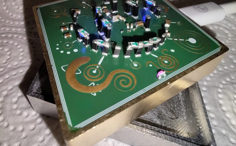
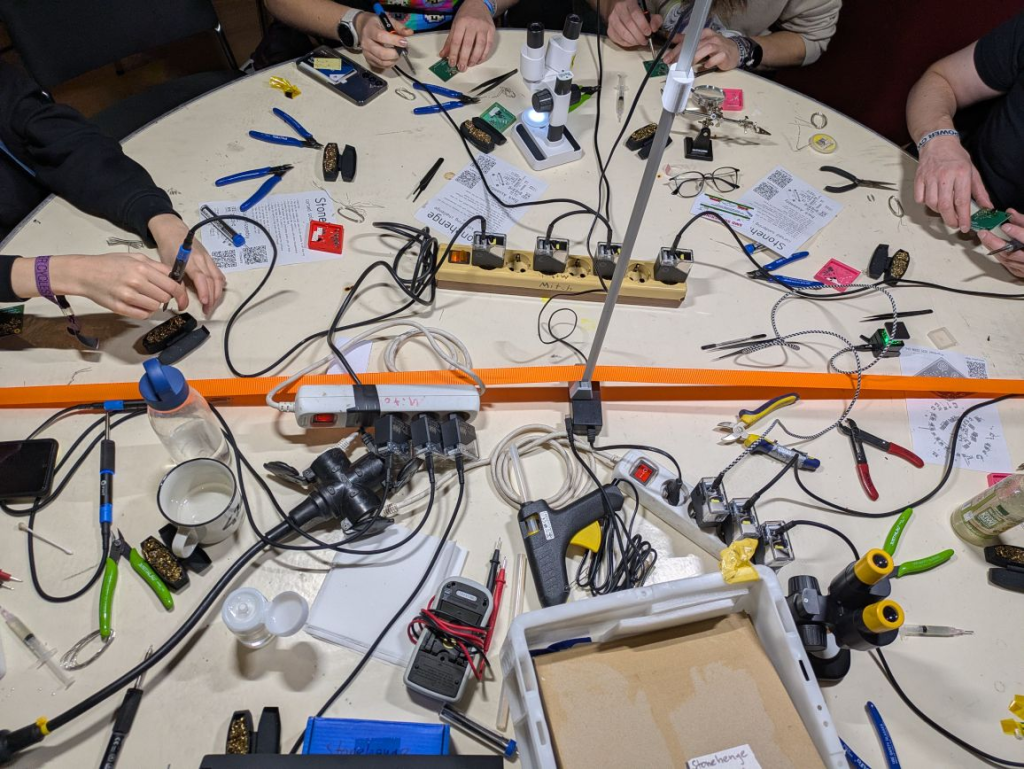
During one of those evenings in the #CCCAC hackerspace talking about stuff and shitposting the concept of stacking components like a tori was discussed, and shortly after that the idea of the Stonhenge PCB was born. It is not quite clear who and how came up with it, but I liked the idea and decided to start working on it. It sure makes a good cursed soldering challenge.
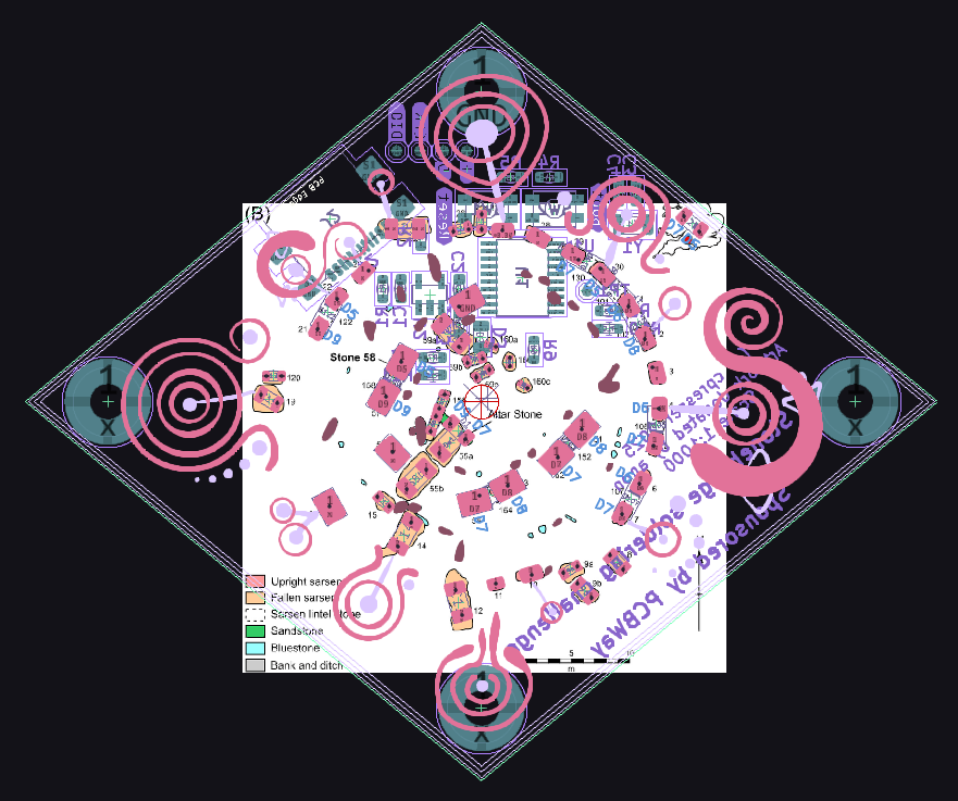
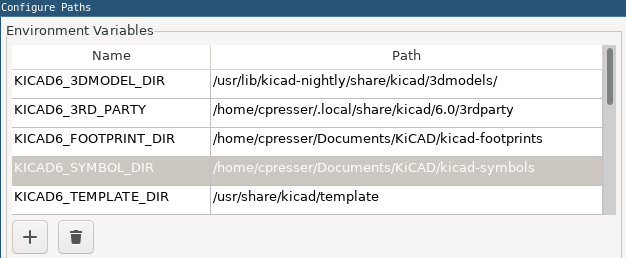
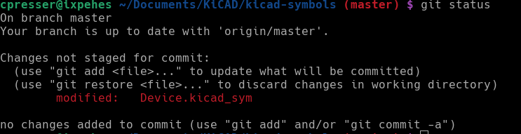
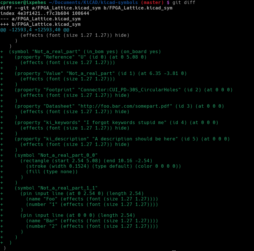
The PCB design was done in KiCad, modifying existing footprints and their 3D models to get a nice preview. The position and size of the stones were extracted from a drawing on wikipedia. Turns our every stone has a name/number, so I did reuse them in the PCB design to keep things simple. The whole project lives in a git repository, check it out if you want to look at more details.
Because everything needs LEDs, the ‘top’-stones are downward facing LEDs.
The board outline is a rhombus shape inspired by artifacts from the Bell Beaker culture which is related to the construction of Stonehenge. The silkscreen and copper artwork (which I did not do myself – it was gifted by friends) also draws inspiration from neolithic items.
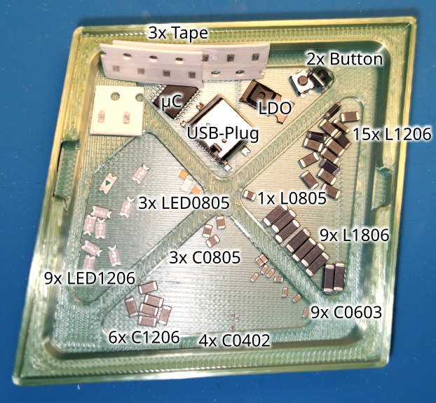
I made kits of this project that were available at #HardwareHackingArea at the dutch hackercamp #WHY2025 and during the #39c3 congress. The earlier #WHY2025 kit was very rushed and had some small issues. There are differences to the latest version – for details check the README in the git project. The kit has all the parts required and a nice 3D-printed base for the PCB and temporary parts storage.
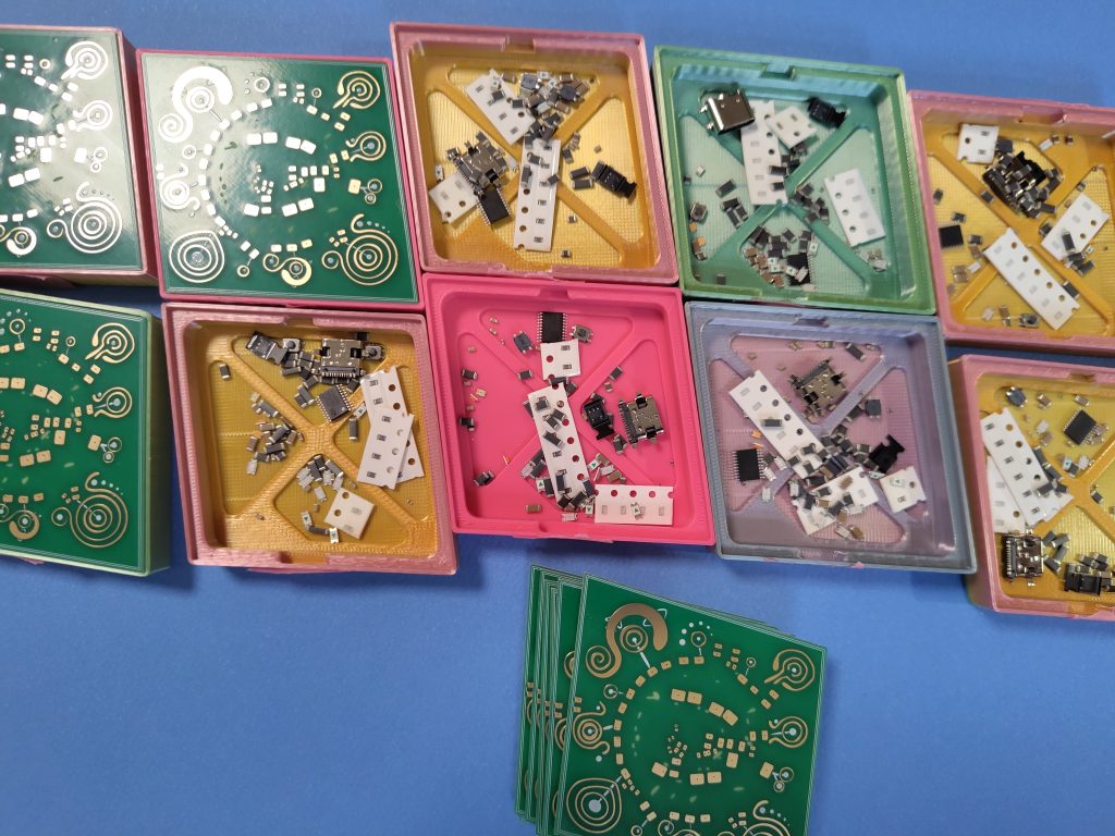
The #39c3 kits were partially sponsored by PCBWay. Interestingly enough they did contact me via this blog and offered to sponsor some PCBs. I took that offer since I was about to order PCBs for this project anyway. The earlier version for WHY2025 was made by JLC, and the prototypes were ordered on aisler. Here is a side-by side comparison of the 3 variants. Can you guess which one is which?

- Left: PCBWay
- Center: Aisler
- Right: JLC
I am really happy with the sponsored boards. They look excellent, the solder mask is ‘less green’ than on the others, which gives a better contrast with the parts and looks a little better with the LEDs turned on. PCBWay sure did a nice job, shipping was also fast and I had no issues with customs/import taxes.
Apparently the kit was a success at #39c3, all 65 of them were handed out to hackers which had fun assembling them. Unfortunately the success rate was not good, there was not enough time to finish for most people and its not the best environment for such a challenging soldering job – especially when you are trying to learn doing tiny and unusual joints. While a experienced (and fast) person can assemble both sides in about 30-45minutes, a hacker that is new to this will surely need more than 2-3 hours. The workshop was only 2h30min, any longer also would be bad. Most people can’t concentrate for that long. So I am considering making it easier: the next iteration will at least have a different USB-Socket which has less pins with more spacing.
The software utilizes the ch32fun framework by cnlohr, the original code was written by Casartar during WHY2025. It has evolved a little since and now does proper PWM charlieplexing of the LEDs. The RISC-V toolchain is reasonably accessible (at least on my ubuntu based linux machine). Together with the isp55e0 bootloader one can upload software without the use an extra hardware interface.

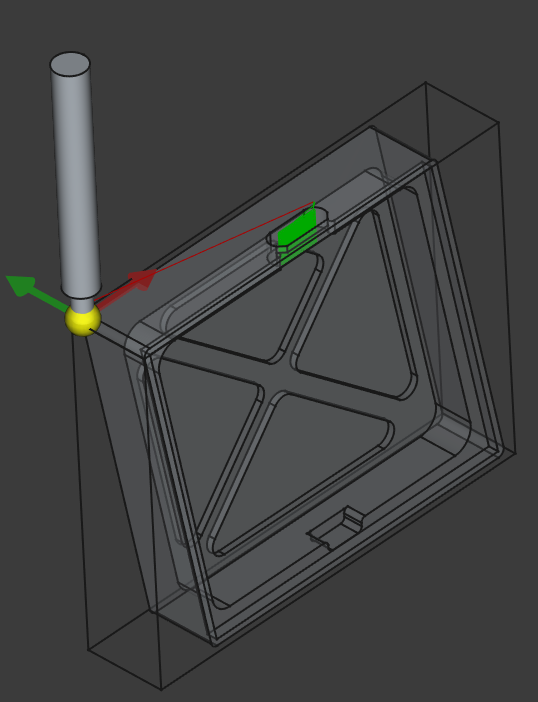
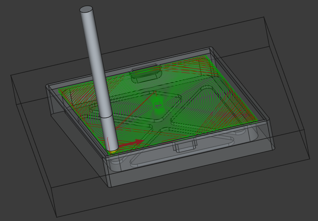
Because I can, I also made one cradle from brass. To practice I also made one from aluminium (brass is rather expensive), its weight feels identical to the 3D-print. The brass is quite heavy, it gives a totally different feeling when you are holding it. All of them were milled on the desktop CNC machine in the CCCAC hackerspace. Since the crade was modeled in FreeCAD it was only logical to also make the toolpaths in FreeCAD.
I want to thank all the people that have helped making this project a success!
- The CCCAC hacker-space for somehow coming up with the idea as a shitpost
- The anonymous person that donated the artwork
- Casartar for helping with debugging, bring up and making the STM32 firmware
- All the friends that helped with component selection, 3D-Printing and encouragement
- The people that helped kitting (making kits by sorting and counting components)
- Workshop participants
- All the HardwareHackingArea people
- PCBWay for sponsoring the boards for the #39c3 workshop
- The authors, maintainers and contributors of all the open source software used

