Earlier this year I started to look at food deliveries, more specifically fresh and local vegetables and fruits. There are quite a few companies that provide that service in Germany. Really nice.
I found a local one that delivers to my home. They offer a convenient web shop where I registered.
Vulnerability ‘research’
The weird part was the registration confirmation: they did set the initial password to my post-code. That immediately caught my attention. The user names are numeric and seem to be incrementing. That can’t be good. So I wrote a small piece of python code that just enumerates users and tries to login with post-codes from the area. And bingo, I got quite a few successful logins. I did verify one of them by looking at the user profile of the poor person that did not change their password. And yes, I could see personal data.
Since my goal was not to steal data I stopped there and did concentrate at the API again. I did some googling to see if there are similar shops. And yes, actually quite a few. They are all provided by oekobox-online.de. A quick check of a arbitrary other shop in another part of Germany proved that the same method of guessing the postcode and just enumerating the user-ids also worked to perform a successful login.
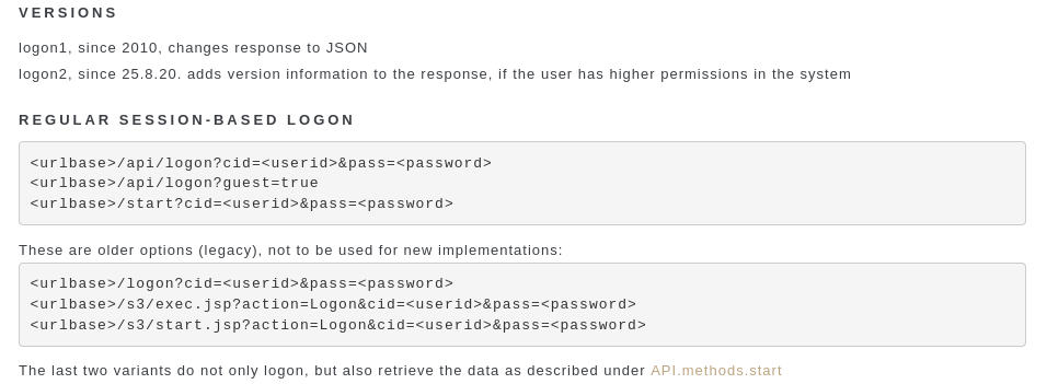
The API is actually well documented by the vendor:
API documentation
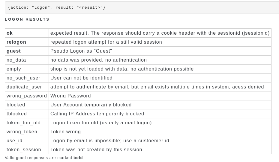
I personally think that a verbose API answer like in the table below adds to the problem. This allows the attacker to first figure out if a user-id is valid before starting to guess the password. Instead the API should just return success of fail, but now why it failed.
API documentation, return codes
The tblocked response was also not well implemented. First of all, it took quite a while for me to be blocked. And even if one is blocked, logins with the correct username/password combo still work.
Contacting the vendor
I did contact the vendor the same day (06.01.2021) and received an answer less than 24 after that. This seems to be one of the few cases where responsible disclosure actually works.
The communication was friendly even though we have quite different opinions about the actual issue. The vendor was already aware of it, but because customers like the easy workflow did not change it.
Nevertheless, a few weeks later (02.02.2021) I received a mail with promising news:
Affected customers have been informed
The rate-limit is now better enforced
Login via user-ID will be disabled soon. Only logon via email-address will be possible
Better passwords will be enforced step-by-step in the next weeks
To be honest, I did not check if all of that is actually properly implemented now. I am to lazy for that.
In one of my pen’n’paper groups we are playing “Niobaras Vermächtnis“. One of the riddles given in it involves solving a sudoku.
Its a variant of a regular sudoku called “greater than sudoku”, or in german “Vergleichssudoku”. Since I am to lazy to solve such a thing manually, I looked for a constraints solver to do that for me. I have never used something like that, so I started looking into different options:
prolog -> I checked the wikipedia page and decided its to complicated for me^^
clasp -> there was a python binding, I played around with that, but its python2 only
z3 -> it has python3 bindings and a sudoku example. So lets use that.
I started from the example and added the greater-than constraints. They are encoded as strings, in horizontal and vertical direction.
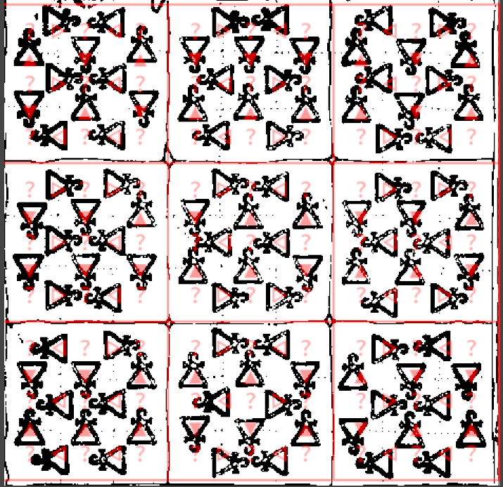
Because the solver did not work, I added a hacky visualization to check the constraints visually. Then used some image processing to overlay that with the original riddle
Constraints visually overlayed
I did quite some more checking, and finally decided to test a known good sudoku. I found this one which solves fine
Thus, the reasonable explanation was that my solver is fine, but the riddle is not. Turns out, somebody already made the same discovery as me.
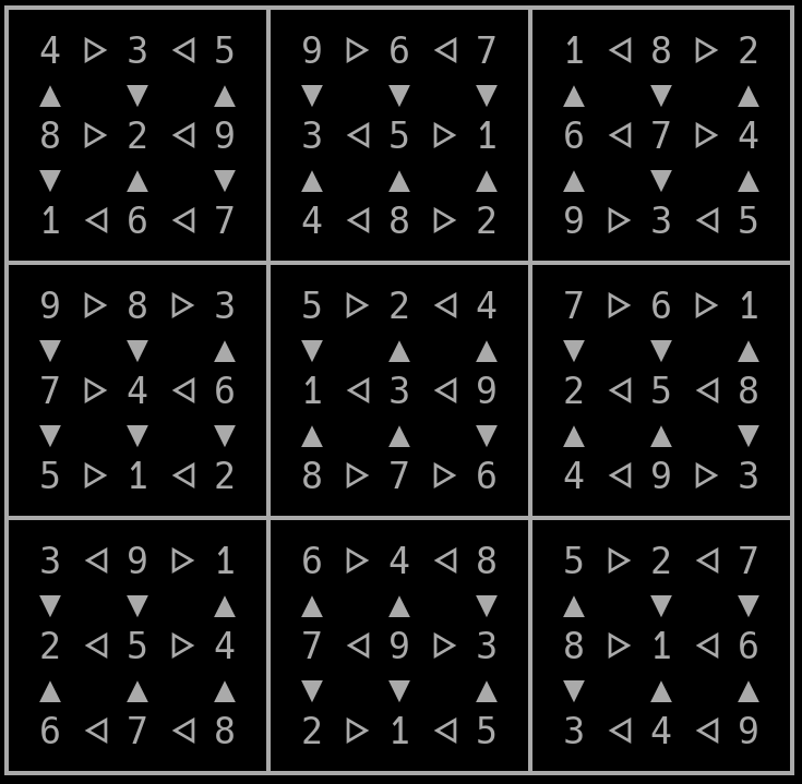
The people over at a DSA fanpage asboran.de already figured that out more than two years ago. After applying their proposed fix, the solver finally returns sat and produces an output:
The solved(?) sudoku
Here is my code if you like to laugh about it, or copy it. License is the same as the example I copied it from
from z3 import Int, Solver, And, Distinct, If, sat;

debug = False

# most of this code was taken and copied from the example at
# https://ericpony.github.io/z3py-tutorial/guide-examples.htm

# other reference for 'greater than sudokus'
# https://github.com/kit1980/grid-puzzle-solver/blob/master/greater-than-sudoku.ecl

# From niobaras vermächtnis (does not work)
# Horizontal constraints
GH = ["><><<>",
      "><<><>",
      "<<<>><",
      ">>><>>",
      "><<<<<",
      "><>><>",
      "<>><><",
      "<><>><",
      "<<><<<"]

# vertical
GV = ["<>>>><",
      "><>>><",
      "<><><<",
      "><><<>",
      "><<<<>",
      "><<>><",
      "<<><<>",
      "><><><", # original constraints with error
      "<<<>><"]

#         | this char was changed
GV[7] = ">>><><"

# from: https://plus.maths.org/content/puzzle-page-77
# we know a solution for this!
# Horizontal constraints
GH1 = ["><><<>",
      "<<><<<",
      "<<<<<>",
      ">>><<>",
      "<>>><>",
      ">>>><<",
      "<<<>><",
      "><<<><",
      "<>><><"]

# vertical
GV1 = ["<>><<<",
      "<><><<",
      "<>><<>",
      "><<>><",
      "><<>>>",
      ">>>>>>",
      "><<><>",
      "><><>>",
      "<>><<<"]

# very hacky visualization
def print_matrix(m):
  print("\n?????????????????????????????????????")
  lineidx=0
  for line in range(9):
    print("?", end='')
    colidx = 0
    for col in range(9):
      print(" {} ".format(str(m[line][col])), end='')
      if (col+1) % 3 != 0:
        ch = u"\u140a"
        if GH[line][colidx] == ">":
          ch = u"\u1405"
        print(ch, end='')
        colidx+=1
      else:
        print("?", end='')
    if (line+1) % 3 == 0:
      if (line != 8):
        print("\n?????????????????????????????????????")
    else:
      a = ["i"]*9
      for foo in range(9):
        a[foo] = u"\u25bc"
        if GV[foo][lineidx] == "<":
          a[foo] = u"\u25b2"
      print("\n? {}   {}   {} ? {}   {}   {} ? {}   {}   {} ?".format(a[0], a[1], a[2], a[3], a[4], a[5], a[6], a[7], a[8]))
      lineidx+=1
  print("\n?????????????????????????????????????")


## Begin adding constraints

###Jede Zahl nur eine Stelle; jede Spalte, jede Zeile, jedes Quadrat darin einmal jede Zahl.

# 9x9 matrix of integer variables
X = [ [ Int("x_%s_%s" % (i, j)) for j in range(9) ]
      for i in range(9) ]

#Jede Zahl nur eine Stelle;
# each cell contains a value in {1, ..., 9}
cells_c  = [ And(1 <= X[i][j], X[i][j] <= 9)
             for i in range(9) for j in range(9) ]


cols_c = []
rows_c = []
for i in range(9):
  # jede Zeile,
  # each row contains a digit at most once
  rows_c.append(Distinct([X[i][j] for j in range(9)]))

  # jede Spalte,
  # each column contains a digit at most once
  cols_c.append(Distinct([X[j][i] for j in range(9)]))


#jedes Quadrat darin einmal jede Zahl.
# each 3x3 square contains a digit at most once
sq_c     = [ Distinct([ X[3*i0 + i][3*j0 + j]
                        for i in range(3) for j in range(3) ])
             for i0 in range(3) for j0 in range(3) ]

# the basic sudoku constraints
sudoku_c = cells_c + cols_c + rows_c + sq_c

# build our DSA horizontal constraints
xl= [0,1,3,4,6,7] # have a stupid lookup-thingy, only 6 out of 9 items have a constraint
h_c = []
for lidx, line in enumerate(GH, start=0):
  for cidx, c in enumerate(line, start=0):
    if c == ">":
      h_c.append(X[lidx][xl[cidx]] > X[lidx][xl[cidx]+1])
      #print("X{}_{} > X{}_{}".format(lidx, xl[cidx], lidx, xl[cidx]+1))
    else:
      h_c.append(X[lidx][xl[cidx]] < X[lidx][xl[cidx]+1])
      #print("X{}_{} < X{}_{}".format(lidx, xl[cidx], lidx, xl[cidx]+1))

# build our DSA vertical constraints
v_c = []
for ridx, row in enumerate(GV, start=0):
  for cidx, c in enumerate(row, start=0):
    if c == ">":
      v_c.append(X[xl[cidx]][ridx] > X[xl[cidx]+1][ridx])
      #print("X{}_{} > X{}_{}".format(xl[cidx], ridx, xl[cidx]+1, ridx))
    else:
      v_c.append(X[xl[cidx]][ridx] < X[xl[cidx]+1][ridx])
      #print("X{}_{} < X{}_{}".format(xl[cidx], ridx, xl[cidx]+1, ridx))

if debug:
  print("Cells 1..9:", cells_c)
  print("Rows:", rows_c)
  print("Cols:", cols_c)
  print("SubSquares:", sq_c)
  print("Horizontal:", h_c)
  print("Vertical:", v_c)
  for co in sudoku_c + h_c + v_c:
    print (co)

# print a empty matrix so we van visually inspect the constraints
empty = [["?"]*9]*9
print_matrix(empty)

# create a solver, add all constraints
s = Solver()


s.add(sudoku_c + h_c + v_c)
if s.check() == sat:
    print("done")
    m = s.model()
    r = [ [ m.evaluate(X[i][j]) for j in range(9) ]
          for i in range(9) ]
    print_matrix(r)
else:
    print ("failed to solve")

print (s.statistics())
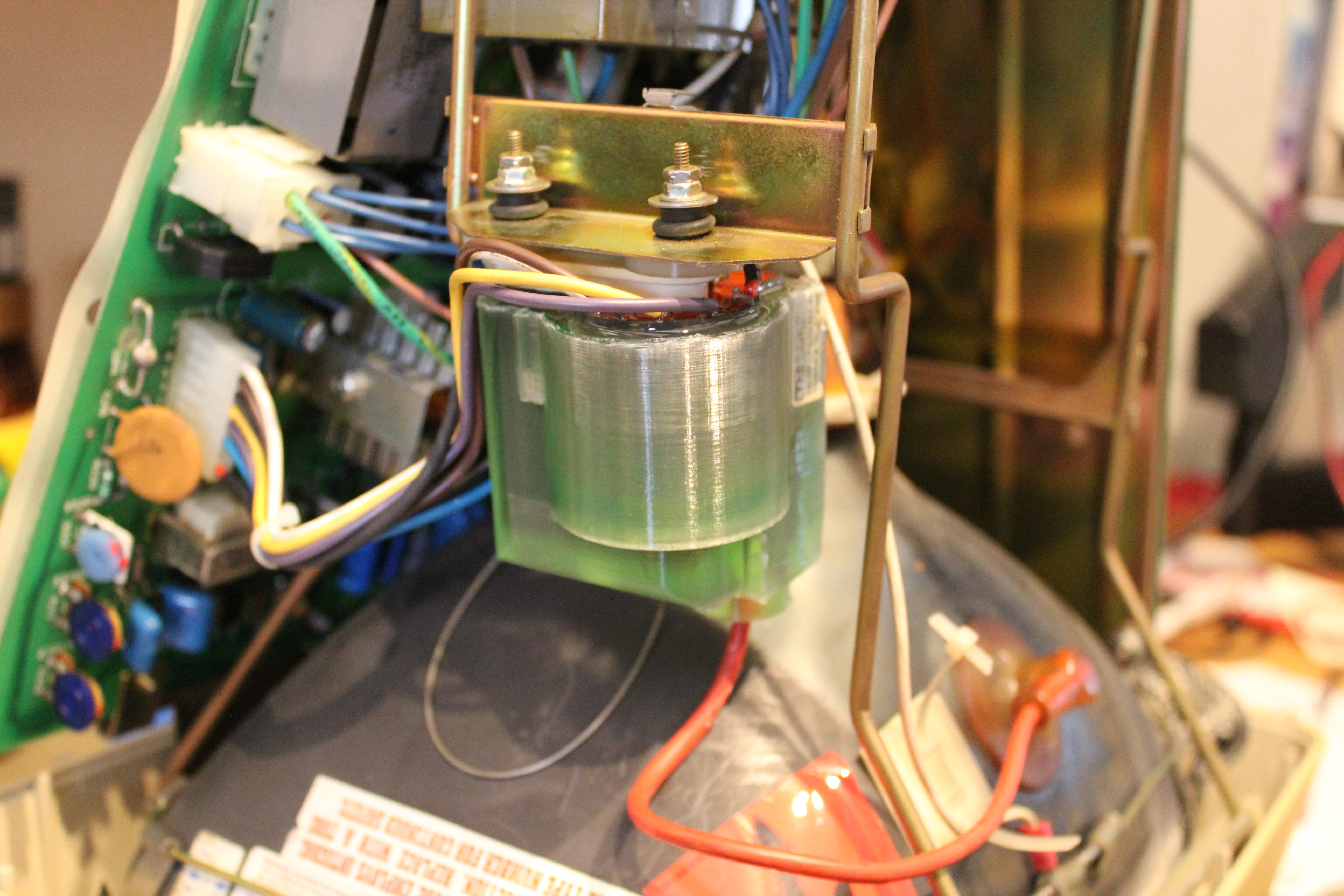
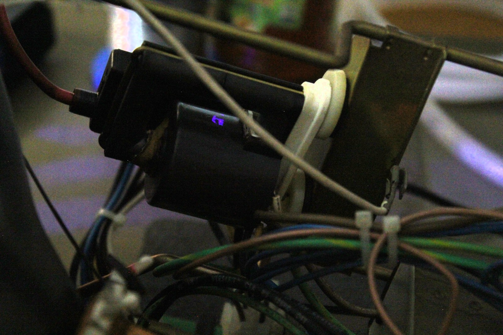
Unfortunately my VT220 did not work well. The flyback transformator is leaky. It can be heard and smelled (the ozone generated by the arc). In a low light environment the arc is also visible (blue-violet spot in the center of the picture).
flyback transformer with visible arc
Most resources on the internet suggest to just get a replacement. Some comments even say it is dangerous to try a repair, but fail to mention exactly why. Getting a replacement is pretty hard for such an old device. I checked the google-search, ebay and hr diemen. But I was not successful.
I choose to do something similar. Use epoxy to re-seal the transformer. But instead of brushing it on I wanted to add a thicker layer.
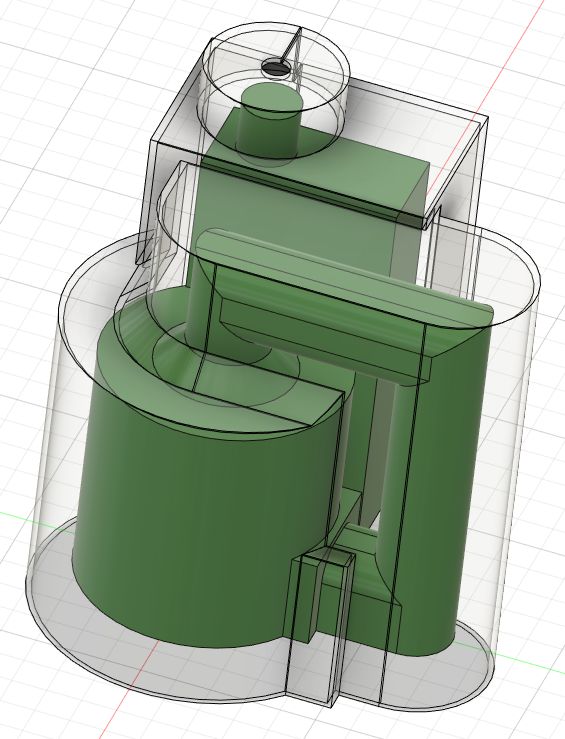
The first step was to make a rough 3D-Model of the existing transformer. Then offset it by 5mm outside to create a mold. That mold was printed in PLA.
3D-Model of the transformer with mold
I did not take any pictures during the casting process. I used hot-glue to fix the flyback in the mold so it does not move while casting. The epoxy used was E45GB with some green pigment mixed in. The volume needed was extracted from the 3D-Model of the mold and the transformer. Make sure to factor in the density of the epoxy, I did not and had to mix a second smaller batch
newly molded flyback mounted in the vt220
As you can see above I did not remove the mold. Its fixed to the epoxy. Next time I will use a release agent.
But did it work? I would say yes. There is no more arcing and I cant smell any ozone anymore. It also more silent, but the typical 15kHz(?) noise is still present.
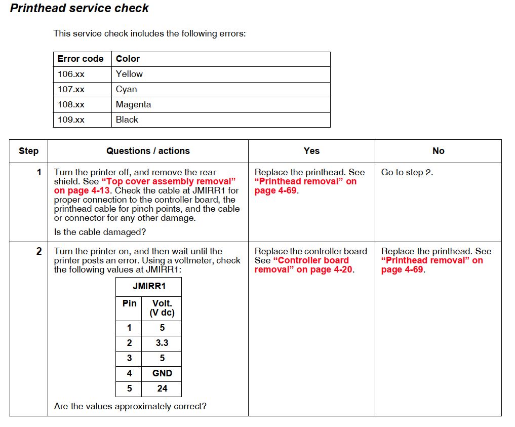
The printer that I have been using for quite some time recently stopped working. The display indicated that the error is “108.08”.
A quick search got me the service-manual for this printer. This is a really great document. It has all the instructions needed to diagnose and fix an error. Detailed disassemly instructions can also be found.
Service instructions for the 108.xx error
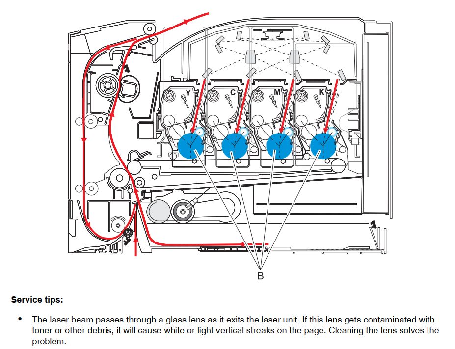
I did all of that, but instead of replacing the printhead I just cleaned it. Over the time dust does accumulate on the windows where the laser light exits the printhead. After disassembly I could clearly see that the windows were cloudy; colorful toner could als be spoted on the windows. My solution was to use a kimtech wipe without any water/solvent to clean the lenses.
The manual actually says to clean those windows, but its on another page/section not directly related to that error.
Illustration how paper and light are routed through the printer
In summer 2019 I have been invited to join the KiCad librarians team. As a librarian my job is to review additions and enhancements of the KiCad-library. Those include footprints and symbols in their respective repository.
All submissions should adhere to the KiCad Library Convention (KLC) which is a set of guidelines to follow when contributing to the library.
Unfortunately there is no on-boarding for new maintainers. And no ‘real’ process for checking contributions. It is up to the reviewer to learn all of that themselves. Thus, I decided to write down a small list of the items I usually check when looking at submission. This list is not comprehensive, so only take it as a starting point!
Could the new symbol be an alias to an existing one
If its an alias, some of the checks can be skipped since the base part is already in the library. Only the dcm file which contains the keywords and description need detailed checking.
A quick check for the base part should be done anyway. This is a great opportunity to find bugs. If possible also fix cosmetic issues if it does not break compatibility.
Are there symbols with similar function already in the library? If yes, does the new symbol conform to the style set by the existing ones?
Sometimes the existing style does not conform to KLC. Then some research should be done to figure out why that is the case. Some symbols are rather old and were made without proper checks
Perhaps the existing symbols needs rework as well. If its just a small amount of work and a non breaking change the contributor can be asked to take care of that as well.
Is the new submission in the correct library section? There are some corner cases or even devices that by no means fit into an existing library. Then a new library can be started.
Is the new symbol a generic or a fully specified symbol
Should there be additional aliases? For example fixed voltage regulators usually come in with different voltage options. It is good to have one alias for each output voltage.
Check the Symbol name
Is it consistent with other similar symbols?
Is the naming according to KLC scheme? For some classes of devices there are explicit rules on how they should be named. For example connectors should include the inserting direction (horizontal, vertical).
Figure out if the part name includes no functional parts. They must be replaced by wildcards. That often includes Temperature or ROHS Variants coded into the package suffix.
Verify names and pin-numbering against the datasheet
Are the pin electrical types helpful for the DRC? Most datasheets give information about pin types. Look for open-collector pins, special power pins, …
In most cases the GND pins can be stacked. Sometimes this also applies to power pins or even I/O.
If the package has an exposed pad or other features (shield, mechanical mounting), is that properly represented in the symbol
NC pins should be on the outline of the symbol body.
Pin layout (which pins go on which side of the symbol)
Again, check for consistency with similar symbols
Perhaps ask the contributor to provide an example how the symbol would be used in a schematic.
Perhaps reshuffle pins (a popular example are XIN and XOUT for a crystal. Its useful to space them by 200mil so Crystal_Small fits between the pins)
Correct ordering (e.g. numbered GPIOs)
For multiple units: does the split make sense?
Metadata
Matches the Datasheet, is consistent with other parts in the lib
Package name at the end of description for standard packages
Keywords exist and make sense, perhaps additional keywords required
Datasheet link exists, page-number anchor if applicable
Footprint
Exactly matches datasheet (check drawing)
Datasheet matches kicad-footprint pin numbering (there are vendors that don’t follow JEDEC)
Filter matches, pin-count not included (unless required)
Perhaps I will make a similar list for footprints in the future.
I recently got me a set of 4 DMX-Controllable LED Lights of ebay for 35€ including shipping.
ebay-listing picture
But they are rather dimm. The article page states
Power Consumption: 15W
LED: 12 pcs * 1W LED (Red*3, Green*3, Blue*3, White*3)
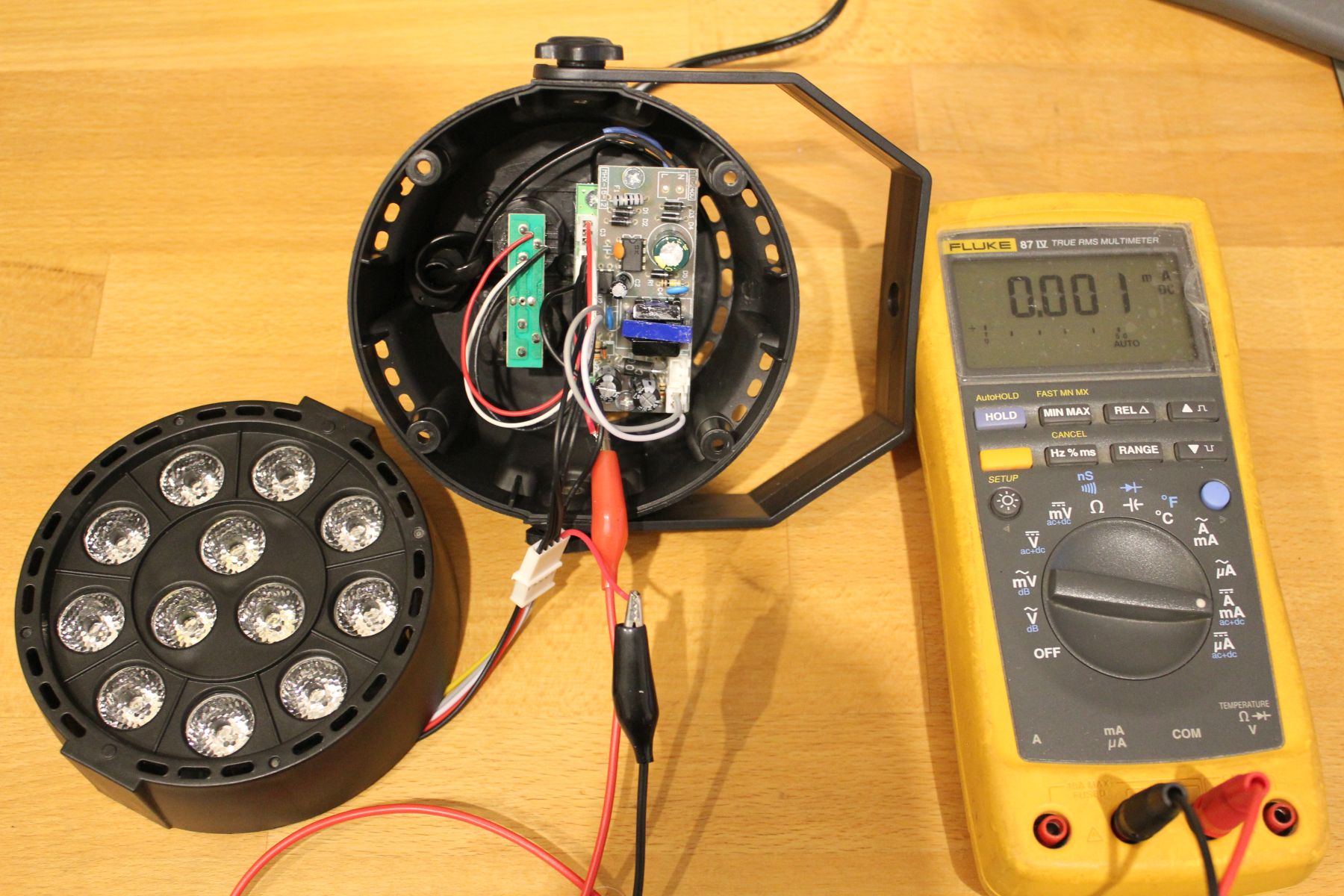
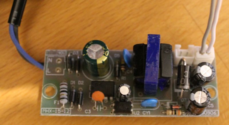
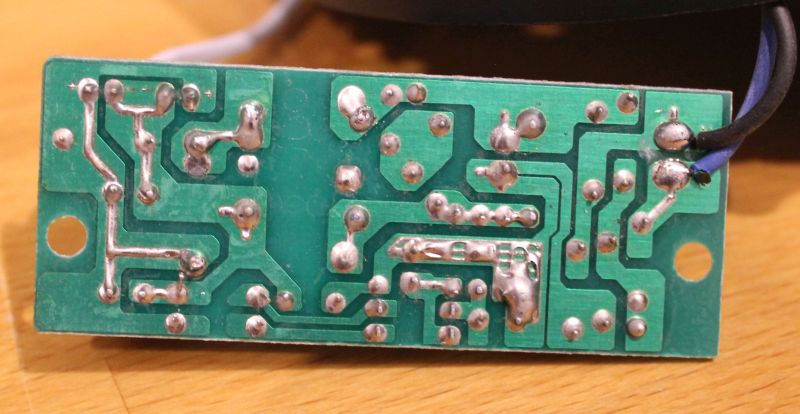
So, lets open one up and check the insides.
When setting all LEDs to maximum (RGBW) the multimeter reads 185mA DC. At just 12V thats not barely enough. Interestingly though, setting it to AC+DC mode reveals a stunning consumption of 340mA, thats almost 4Watt.
But wait, why is there even AC voltage when everything is turned up to full brightness?
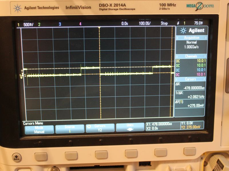
Scope to the rescue!
I put a 1Ohm resistor in series to measure current, so 1mV -> 1mA. The voltage across the LEDs is always 12V, as output by the PSU.
scope showing the current waveform for the blue led
You can see 478us PWM-Period with a on-time of 126us. Thats a DutyCycle of 26% at 100% brightness. That explains the AC current measured earlier. The peak current is ~275mA.
This roughly correlates with the 4Watts measured with the multimeter.
But what about the overall quality? I guess you get what you pay for.
The LED PCB is made out of aluminium and is a decent heatsink. But it is rather thin. The LED-lenses are as described and work properly.
Plastic case seems nice. No problems here
The Control-Knobs are easy to use, the 7-Segment-Display shuts off after a few seconds. Premium feature!
No gamma adjustment. 50% Brightness equals 50% (of max) DutyCycle.
The DMX In- Out-Port are just connected to each other. No RS485-driver to improve signal quality
The internal plugs are JST-XH (clones?), but they saved a few cents by just populating pins instead of complete receptables on the controller board.
The PWM-Base-Frequency of red is different than the other colors. WTF?
Since no DC is > 25% one would expect that the PWM-Periods are interleaved so the current does not add up. But nope, thats not the case.
No resistors in front of the LEDs. So the 3 red LEDs which have a combined Vf lower than 9V are run at the full 12V.
There is no sign of any PFC on the primary side of the PSU.
The PSUs isolation between primary and secondary is garbage. The feedback-opto has all its 4 terminals pretty close to the primary side. Thats less than 1mm.
12V PSU
Conclusion – Next steps
So this is not as bright as I want it to be. And the PSU looks dangerous. So the next logical step is to fix that. I used a lab power-supply to check if each LED actually can handle 1Watt. The answer is yes, but then it gets hot rather quickly. So some sort of cooling is required.
I think the mod will be made with series-resistors in front of the LEDs so they can run of 12V DC. Then all 4 fixtures controlled by one KaratLight Device. Not sure about cooling yet, running this at 12Watt will be to much heat for the aluminium PCB to handle.
Recently I had to work with Atmel START. The basic idea looks promising, a nice GUI to configure the peripherals of your chip so you can start with the actual project faster.
But there are way to many downsides.
It requires a Internet connection
I don’t really understand the whole Idea behind the architecture. It looks like the GUI generates a json which is then send to the Atmel backend that is somewhere on AWS. An archive with source code is generated, downloaded extraced and integrated into the Atmel Studio Project.
There is no offline Workflow. If you want to reconfigure something, you need a internet connection.
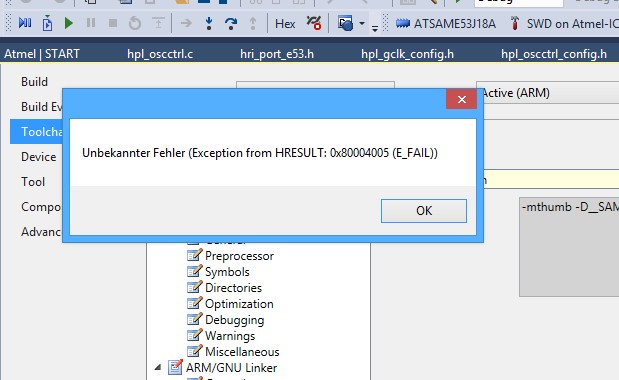
Bullshit error Messages
Look for yourself. This is what I got the 2nd time I tried to update a Project. Funny enough, just doing it again made the error go away. Quality software, yay!
There is also the case that the Backend does an Error 500. I have seen this several times, it seems to be triggered by entering weird values into the GUI fields. Like 10Ghz Clock frequency or so.
It is slow as hell
Changing one checkbox takes about two minutes. The loading time of the GUI is already a minute, then the GUI scrolls really slow and is unresponsive. After doing the change, it takes ~20sec until I am back in Atmel Studio and can hit compile.
By now, I have learned to change the C headers directly. But that means also extra work when I want to add another module via START since I need to manually merge the differences between my local files and the generated ones.
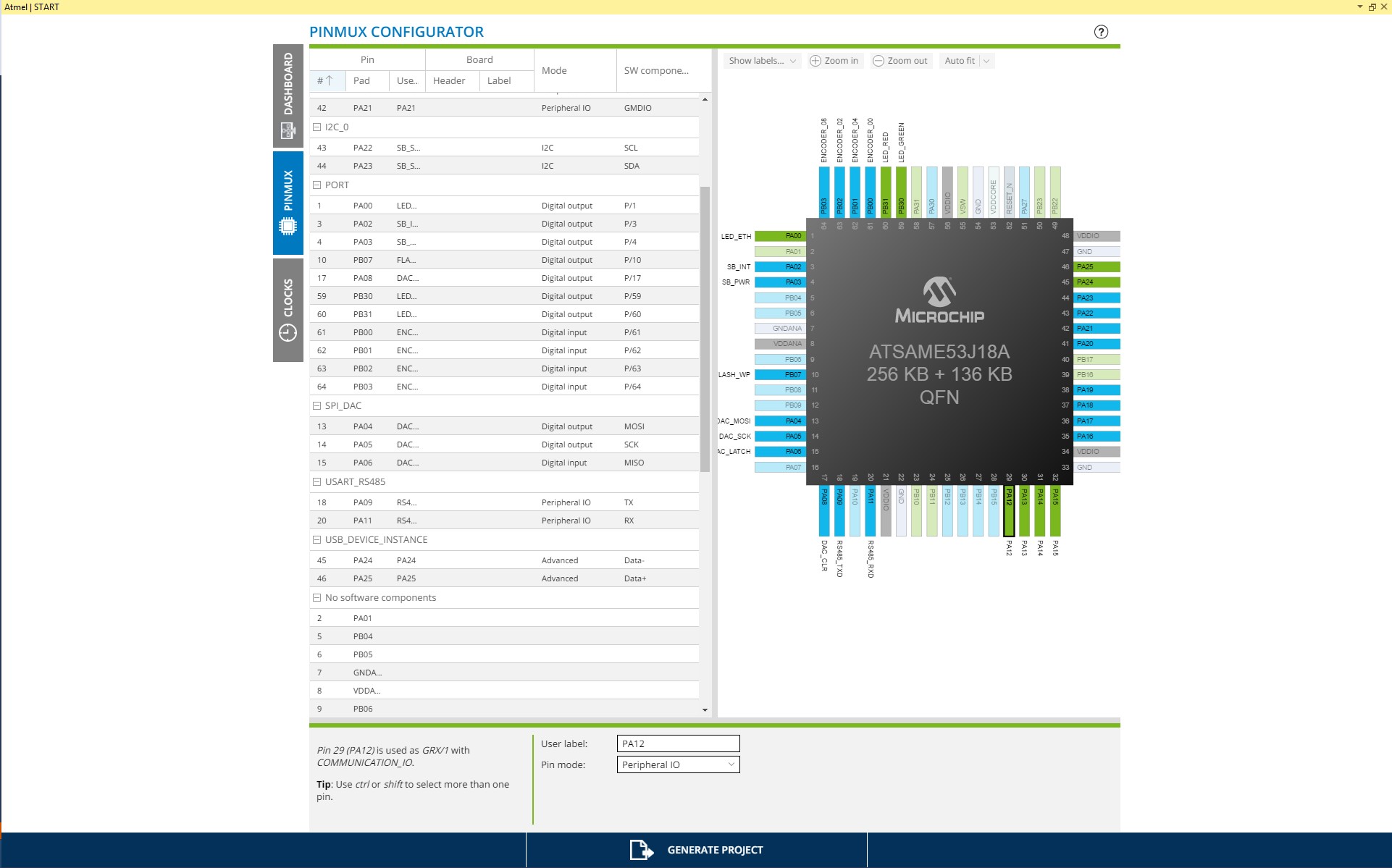
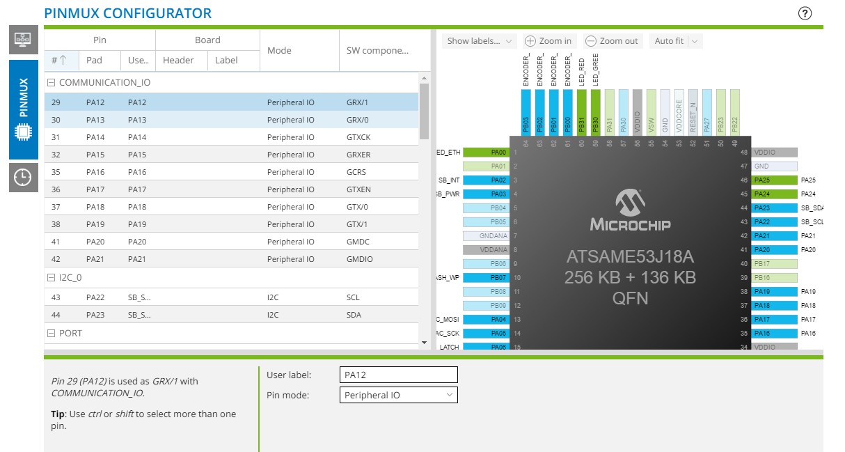
The GUI has usability issues
Labes are cut off and are not visible. Why would the Framework set the same Userlabel as the Pin name. If its the same, its redundant.
The Screenspace is not well used. Resizing windows is a PITA because its so slow.
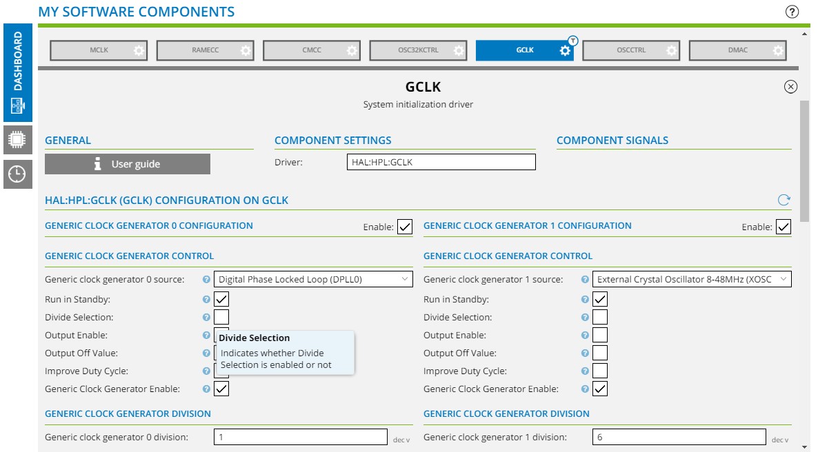
GUI fields description
Here are two prime examples. Why does anyone include a description like this. I can tell this by reading the field name. How about “Checking this box will change the way the divider is calculated. Unchecked means divide by N-1, checked divide by 2^n-1”.
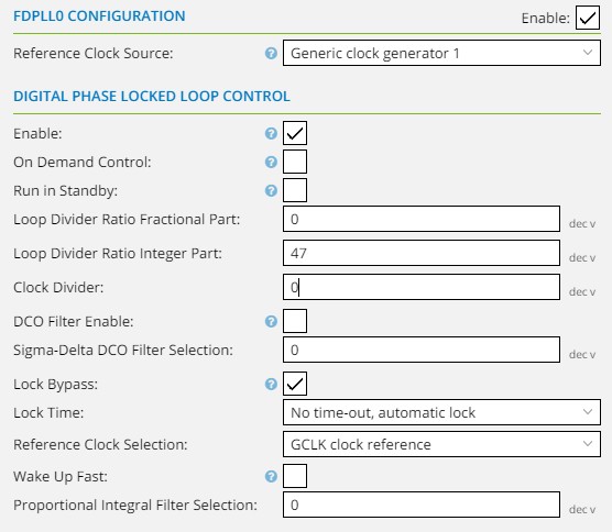
GUI fields functions
The clock divider for DPLL XOSC input does not work inside Atmel START. So all the other modules assume a wrong clock frequency. However, the chip does behave as predicted.
There is also no hint that this divider only applies to XOSC, but not for the GCLK input.
To make tings worse, there is a field called “Reference Clock Source” and one called “Reference Clock Selection”. Really? It doesn’t even make sense after looking into the data sheet.
GUI fields function, again
If there is a checkbox, that disables a function, also disable all the related fields so its obvious to the user that they have no function.
This feature is implemented for most modules, but is missing for the USB Configuration. So the user has no visual hint why the USB descriptors are not working.
Clock Configuration
This is actually pretty nice, to have a schematic on clock distribution. Good start. Next, please add the respective frequency of each clock on its configuration page. The values are already calculated, I can see them in the clock selection dropdown of the usb module. Why not just display the frequency on the GCLK or OSCCONTROL page as well?
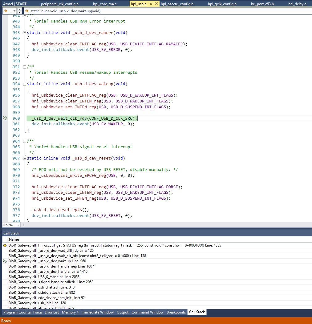
There are bugs
Well, all Software projects have bugs. But in this case it really sucks. Imagine spending an hour to get clocking right because the GUI is broken. Then finally hit compile and the code hangs during USB initialization. Looks like the DFLL vs. DPLL decision making does not work. Had to patch this by hand, now its good. But again, I need to redo this patch every time after project reconfiguration. Great.
There is no central place for the code, and thus on issue tracker
So, I have spotted a few bugs. That happens all the time, no big deal. Usual workflow is to create a patch and do a pull request. But not with Atmel Start. There is just nothing one can do. Every other user has to find and fix that issue again and again.
Missing functionality
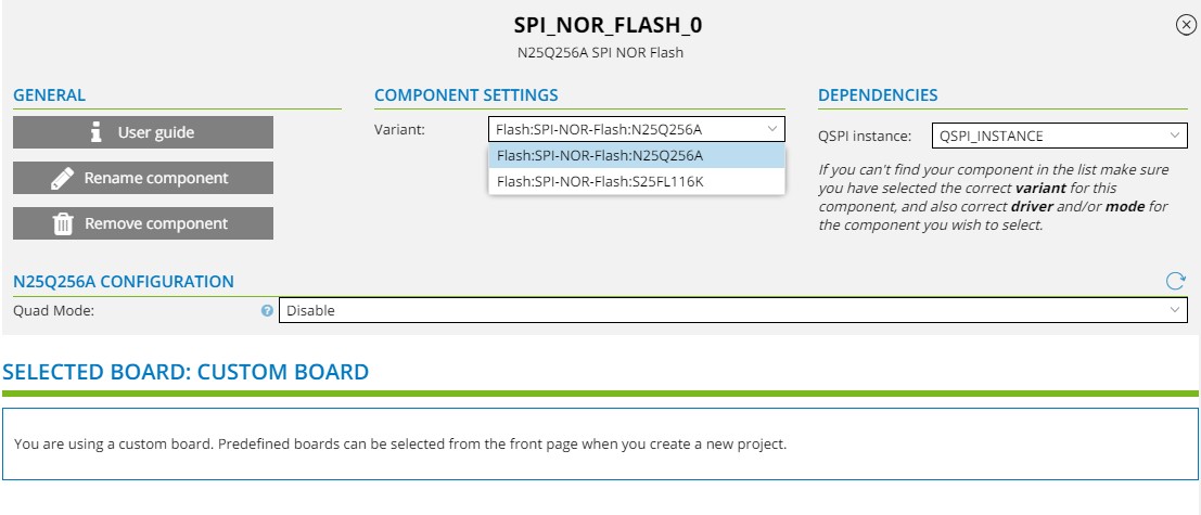
A few things that hit me on the first day
– NOR-Flash driver only talks QSPI, not ‘regular’ SPI
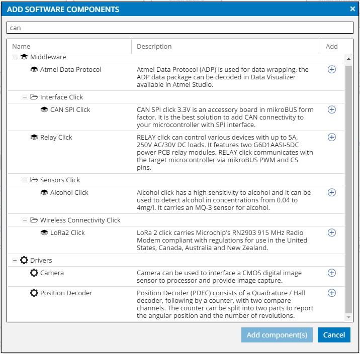
– There is no CAN driver, only a example for a CAN cip attached via SPI. No use for a CPU with a buildin CAN
– The IP Stack has only LWIP 1.4, even though LWIP 2.x is stable. So no IPv6 support
I can’t go back to ‘regular’ ASF
It looks like newer chips are only supported via START. So I can’t go back to the ‘just have some code and makefiles’ approach of ASF. There is just no support in ASF for newer chips. Now I am stuck with this START shit.
Unfortunately this is a work project, so I can’t choose to have a different CPU. And supporting it in libopencm3 is nothing my employer is willing to spend any resources on.
So I am out of options and stuck with this shit. Even though there are some nice new features, like the generic-io-API for serial connections, … this does no make me happy.
Dear Atmel/Microchip: Please just put the libs on github and attach some Makefiles for ease of use. I promise to send patches 🙂
For this years EMF camp I was traveling together with the belgian embassy. We had two busses filled with people and material to drive from belgium to the campsite and back.
One of the busses had a blown tire on our way, that was fixed by fitting the spare:
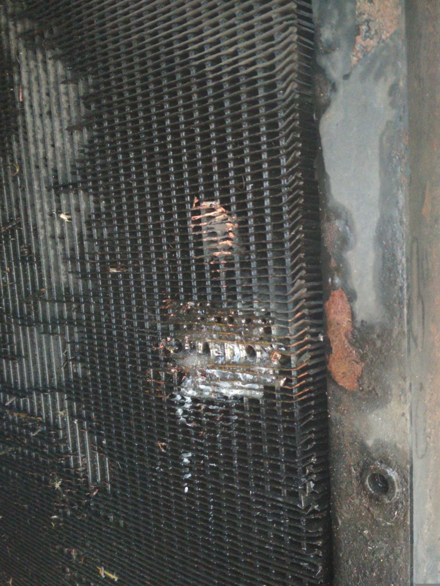
On our return trip however, we had a major issue. The radiator was leaky, as seen in this picture. The water on the road used to be in the cooling system.
We did discuss how to fix it. One option was to just put an egg into the cooling liquid, in the hope that the protein would coagulate and stop the leak. But that is a process we can’t control, so we switched our focus to other methods.
Next up was soldering. We had lots of solder-equipment with us, after all we were coming form a hacker-camp. But soldering on a heat-sink is doomed to fail. Perhaps we could have done it with a propane torch, but we did not have one with us.
All that was left was to glue it. I had some 5-Minute-Epoxy at hand. First we drained the radiator and dried it with the hot-air. Then some cleaning using wire-brushes and isopropanol was done. The epoxy was mixed and stuffed into the radiator with tootpicks and other pointy objects, then heat-cured with the hotair for 30minutes.
This is how it looked after the curing:
Its messy and ugly, but it did seal the leak. I did expect that it would still leak a little, but to our surprise it was perfectly sealed. The cooling system was even able to build up pressure again.
With that repair we made it back over the canal back to belgium 🙂
I am in need for a z-measurement device for my cnc. So I checked ebay and got me a used mitotuyo depth gauge for ~60€. It has an ‘SPC’-Interface for digital readout. Fortunately there is some information on the Web on howto access that interface.
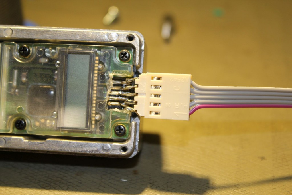
DIY connector
I didn’t want to buy an expensive Mitutoyo-cable, so I decided to solder on my own connector.
Pinout is:
1. GND (red cable)
2. Serial Data Out (OpenCollector)
3. Serial Clock Out (OpenCollector)
4. (unused)
5. Request In
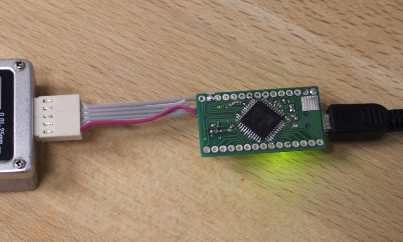
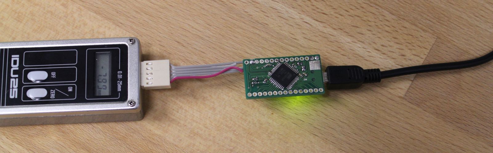
The USB-Conversion is done by a tinymega microcontroller board which features an Atmega32U4 CPU. With the LUFA USB-Stack it presents itself to the host as a virtual serial port.
The implementation of the SPC-Protocol decoding is pretty straightforward. Send a request on one pin, read in data via SPI. I chose to do all of this in software with one interrupt (not using the SPI peripheral of the CPU). You can see my implementation here on github.
caliper + tinymega
Now all that is left is to hook it up to linuxcnc. I haven’t done that yet, but most likely it only requires 10 lines of python to generate a HAL-Module.
Controlling WS2812 LED-Pixels from an Raspberry-Pi can be done. Other people have done this before: https://github.com/jazzycamel/ws28128-rpi/
My approach is different, but not that new either. I already implemented similar code for the Lightpainting-Stick-Clone.
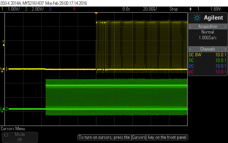
To get the required timing with the SPI we can output some patterns to make it look like the WS2812-Protocol.
The yellow line is MOSI (DIN). The 50us Reset is visible on channel 2.
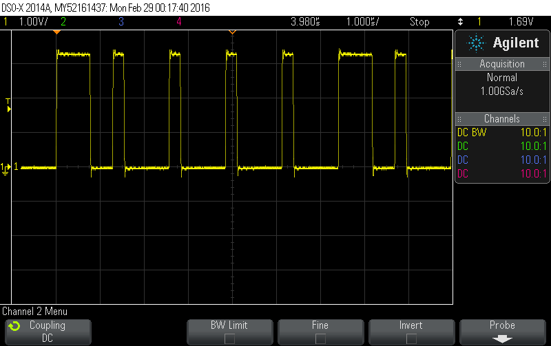
Closeup of the actual timing. This image shows the first 7 bits (1000010)
However, there are some issues as metioned in the inline-comments. At first it seems like the code does not work when sending dmx-data with ola_dmxconsole. Once there are more changes in a short period of time, the pixels start to react. My guess here that this is related to the scheduler of the kernel. When as the kernel switches tasks the SPI output-stream gets interrupted, thus making the timing invalid. I will investigate this further.
void SPIOutput::IndividualWS2812Control(const DmxBuffer &buffer) {
  /*
   * This is an hack!
   *
   * Basically the RaspberryPI cant drive WS2812 Pixels because they have
   * some strict timing requirements.
   * Using the SPI-Module we can emulate those pulses.
   * This will only work if the SPI-Module outputs all data in one consecutive
   * stream without any pauses. More recent versions of the Raspberry Kernel
   * seem to implement DMA for SPI which makes this possible.
   *
   * WS2811-Chips have similar timings but not exactly the same as WS2812.
   * Some sources say the most important part is the total period-time
   * of one bit. There are lots of descriptions of WS2812-timing requirements
   * out there, one of them is: (with +-150ns tolerance)
   * 0-Bit 0.25us high, 1us low
   * 1-Bit 0.6us high, 0.65us low
   *
   * Running the SPI at 4Mhz gives us a pulse-width of 250ns
   * Using a 5-bit pattern we can emulate those timings
   *   0-Bit: 10000 (0.25us high, 1us low)
   *   1-Bit: 11110 (1us high, 0.25us low)
   * Those values are not an exact match, but they seem to work for both
   * WS2812 and WS2811 in high-speed-mode.
   *
   * We need to send 8 of those 5-packs for each byte. Those 40 bits are
   * precalculated and stored in a lookup table.
   *
   * To issue an reset, the data-line needs to be low for 50us, thats
   * 200 bits, or 25 bytes. For safety, we will send 27 bytes.
   *
   * Connect the Data-In-Pin of the LEDs to the MOSI Pin of the SPI-Module,
   * ignore the clock Pin.
   *
   */
  const uint8_t reset_bytes = 27;
  const unsigned int first_slot = m_start_address - 1;  // 0 offset
  // We always check out the entire string length, even if we only have data
  // for part of it
  const unsigned int output_len = reset_bytes + m_pixel_count *
                                  WS2812_SLOTS_PER_PIXEL * WS2812_SPI_LUT_LEN;
  uint8_t *output = m_backend->Checkout(m_output_number, output_len, 0);

  if (!output)
    return;

  // set the reset-bytes to zero
  memset(output, 0, reset_bytes);

  // loop over all pixels
  unsigned int output_pos = reset_bytes;
  for (uint16_t px = 0; px < m_pixel_count * WS2812_SLOTS_PER_PIXEL; px++) {
    uint8_t c = buffer.Get(px + first_slot);
    // now output 5 bytes from the LUT
    for (unsigned int lut = 0; lut < WS2812_SPI_LUT_LEN; lut++) {       output[output_pos++] = WS2812_SPI_LUT[c * 5 + lut];     }   }   m_backend->Commit(m_output_number);
}