Repair Samsung S27C590H LED Backlight

This Samsung 27″ monitor recently stopped working and would not stay on. After power-up, it shows the menu and input-source, but then shuts down again. Interestingly that is the same behavior as described in this reddit post. The only comment in that post says

test the LEDs. if one is bad, the entire system enters shutdown

So lets do that (info on how to open that thing is at the end of this post). I started by looking at the negative side of the LED supply on the mainboard. As you can see, I marked of the test-points (LED2) red because that corresponds to the LED stripe that does not work properly. The voltages on the LED test points should be close to zero, the working ones had about 0.8V. The channel with issues was about 18V, but quickly dropped since the controller did detect this and restart the system. The positive supply of the LEDs has 68V. That matches the information from the reddit post.
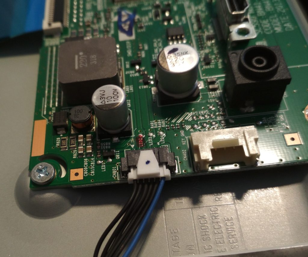
Controller PCB, a white connector with 6 conductors.
A beefy inductor and some caps are visible.

By carefully removing the wires from the LED connector that corresponds to the broken channel I could verify that the rest of the screen is working properly. It stayed on and displayed a picture. Albeit, there was a huge dark streak where part of the backlight is missing. That means we need to remove the backlight and fix it. After some more disassembly, the LEDs could be removed. With a multimeter in diode test mode one of the LEDs was found to be non working. Since I don’t have the correct LED or even something similar (those LEDs seem to have a Vf of 5.5V), the solution was to solder in a zener diode with 5.6V. Fortunately my parts drawer has a set of various zeners.
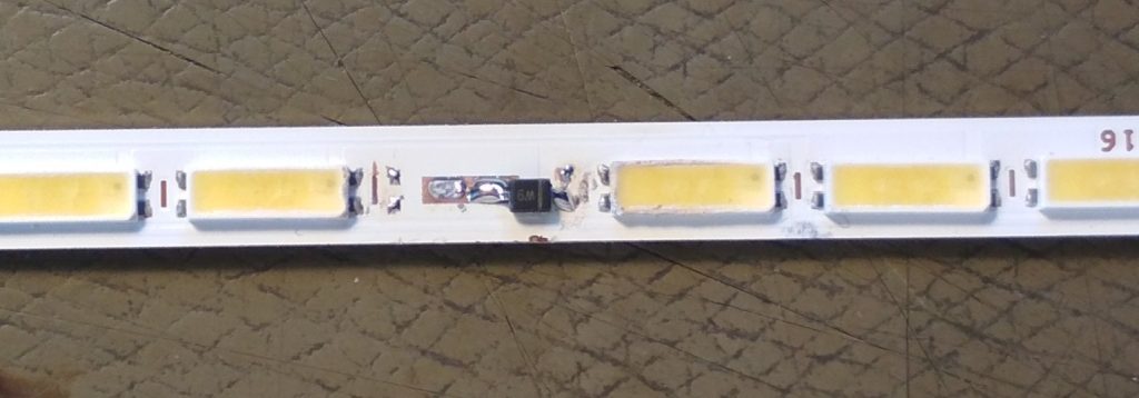
A thin PCB with LEDs
one LED has been replaced with a smol zener diode.
One LED module replaced with a zener diode.

Now the screen just needs to be assembled again.
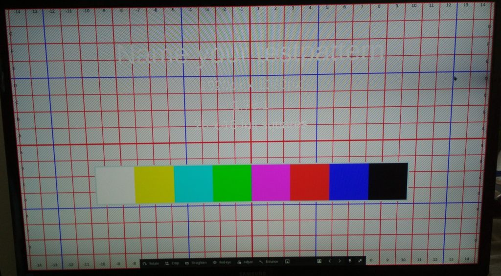
A test-image
on the right side, close to the cursor, there is a dark spot.
A slight dark spot/sliver on the right side

More disassembly pics

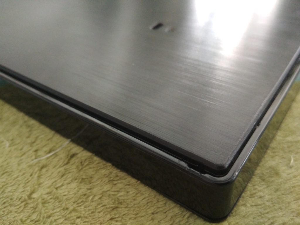
The corner where one can start to remove the back panel.
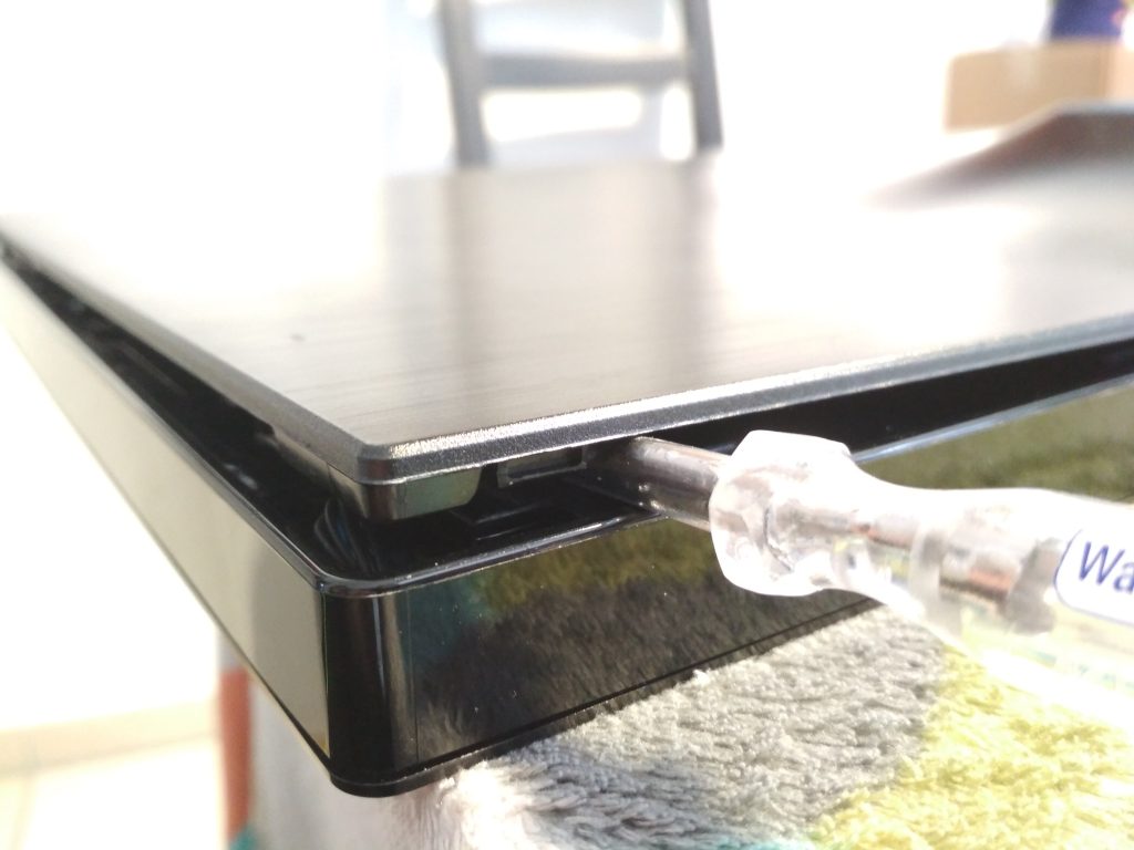
Closeup of the plastic snap thingies of the back panel
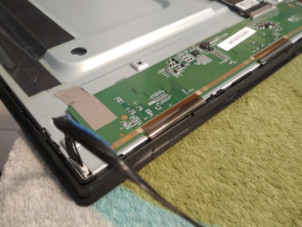
Open screen, display-driver boards at the bottom. LED-Cable on the left. The front bezel is still attached.
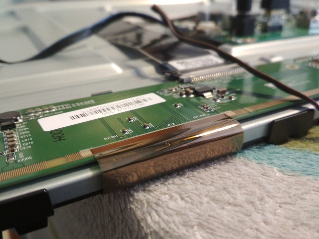
screen with front bezel removed. The flex cable connecting to the glass substrate is visible.
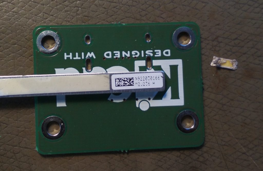
Sticker that identifies the backlight LED strip

El-cheapo China DMX LED Spots

I recently got me a set of 4 DMX-Controllable LED Lights of ebay for 35€ including shipping.

ebay-listing picture

But they are rather dimm. The article page states

Power Consumption: 15W
LED: 12 pcs * 1W LED (Red*3, Green*3, Blue*3, White*3)

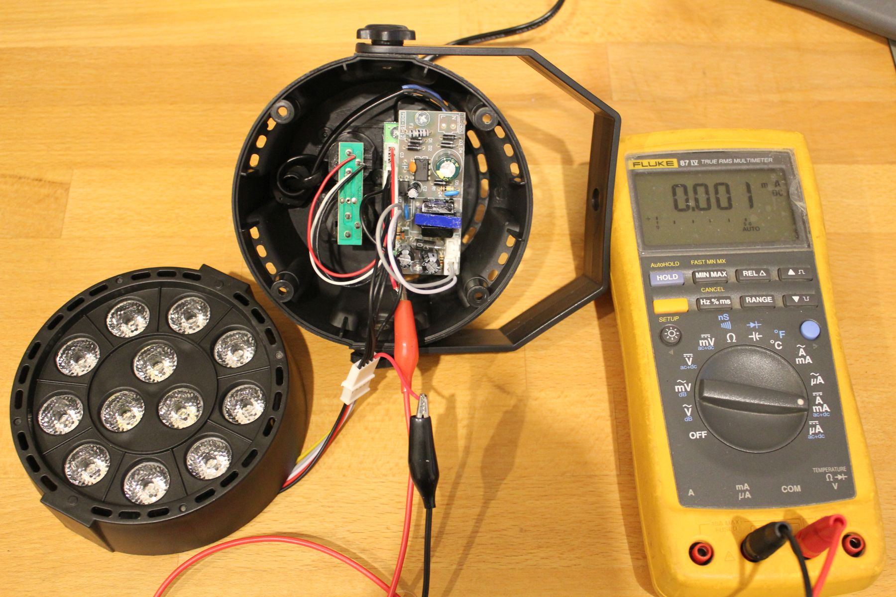
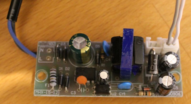
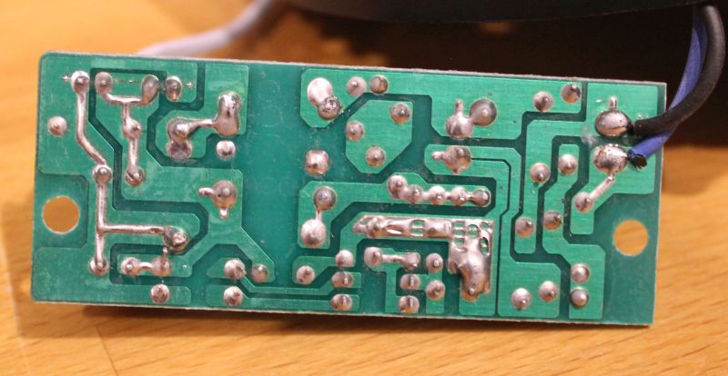
So, lets open one up and check the insides.insides of the led fixture, a multimeter

When setting all LEDs to maximum (RGBW) the multimeter reads 185mA DC. At just 12V thats not barely enough. Interestingly though, setting it to AC+DC mode reveals a stunning consumption of 340mA, thats almost 4Watt.

But wait, why is there even AC voltage when everything is turned up to full brightness?

Scope to the rescue!

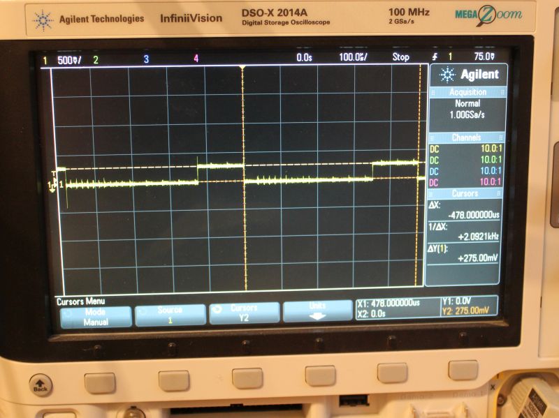
I put a 1Ohm resistor in series to measure current, so 1mV -> 1mA. The voltage across the LEDs is always 12V, as output by the PSU.

scope showing the current waveform for the blue led

You can see 478us PWM-Period with a on-time of 126us. Thats a DutyCycle of 26% at 100% brightness. That explains the AC current measured earlier. The peak current is ~275mA.

  • Red: 780mA, DutyCycle 17us/318us -> 0.5Watt RMS
  • Green: 350mA, DutyCycle 108us/480us -> 0.95 Watt RMS
  • Blue: 275mA, DutyCycle 126us/480us -> 0.86 Watt RMS
  • White: 487mA, DutyCycle 98us/480us -> 1.19 Watt RMS

This roughly correlates with the 4Watts measured with the multimeter.

But what about the overall quality? I guess you get what you pay for.

  • The LED PCB is made out of aluminium and is a decent heatsink. But it is rather thin. The LED-lenses are as described and work properly.
  • Plastic case seems nice. No problems here
  • The Control-Knobs are easy to use, the 7-Segment-Display shuts off after a few seconds. Premium feature!
  • No gamma adjustment. 50% Brightness equals 50% (of max) DutyCycle.
  • The DMX In- Out-Port are just connected to each other. No RS485-driver to improve signal quality
  • The internal plugs are JST-XH (clones?), but they saved a few cents by just populating pins instead of complete receptables on the controller board.
  • The PWM-Base-Frequency of red is different than the other colors. WTF?
  • Since no DC is > 25% one would expect that the PWM-Periods are interleaved so the current does not add up. But nope, thats not the case.
  • No resistors in front of the LEDs. So the 3 red LEDs which have a combined Vf lower than 9V are run at the full 12V.
  • There is no sign of any PFC on the primary side of the PSU.
  • The PSUs isolation between primary and secondary is garbage. The feedback-opto has all its 4 terminals pretty close to the primary side. Thats less than 1mm.

Conclusion – Next steps

So this is not as bright as I want it to be. And the PSU looks dangerous. So the next logical step is to fix that. I used a lab power-supply to check if each LED actually can handle 1Watt. The answer is yes, but then it gets hot rather quickly. So some sort of cooling is required.

I think the mod will be made with series-resistors in front of the LEDs so they can run of 12V DC. Then all 4 fixtures controlled by one KaratLight Device. Not sure about cooling yet, running this at 12Watt will be to much heat for the aluminium PCB to handle.

Using OLA to controll a LED-Sign

Earlier this year my colleague Rüdiger and me build some LED-Letters and mounted them to the building front. The letters themselfes are made of 20mm Acrylic with buildin RGB-LEDs. A 3mm black Acrylic plate was added on top to cover the LEDs and generate more contrast for daylight conditions.

The control is build around the OLA Software. A Raspberry-Pi drives all the components. Two KarateLight devices provide 8 RGB channels each. A USB-Hub (which also poweres the Pi) and a USB-WLAN-Stick make the setup complete. The LEDs are powered by two 320Watt switching-mode PSU. Everyhting fits nicely into a steel cabinet which makes this thing waterproof. In order to organize the cables coming in at the bottom I build two combs which clamp the cables into place.

Since i dont have a cool DMX Application i wrote a few lines of python to generate a simple animation. Basically all it does is calculate a gauss-distribusion which is then shifted from left to right. Its quite simple and not well implemented, but it works: ola.python_fader.

I then use ola_recorder to store a single run of the script into a file. Playback is also done with ola_recorder running inside screen.