I recently got me a set of 4 DMX-Controllable LED Lights of ebay for 35€ including shipping.
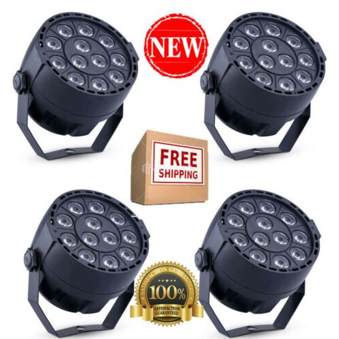
But they are rather dimm. The article page states
Power Consumption: 15W
LED: 12 pcs * 1W LED (Red*3, Green*3, Blue*3, White*3)
So, lets open one up and check the insides.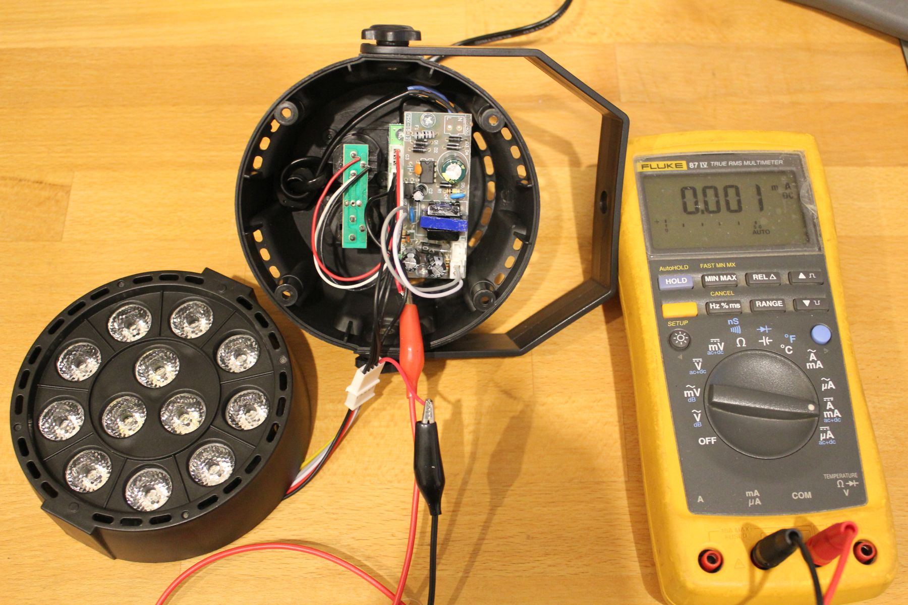
When setting all LEDs to maximum (RGBW) the multimeter reads 185mA DC. At just 12V thats not barely enough. Interestingly though, setting it to AC+DC mode reveals a stunning consumption of 340mA, thats almost 4Watt.
But wait, why is there even AC voltage when everything is turned up to full brightness?
Scope to the rescue!
I put a 1Ohm resistor in series to measure current, so 1mV -> 1mA. The voltage across the LEDs is always 12V, as output by the PSU.
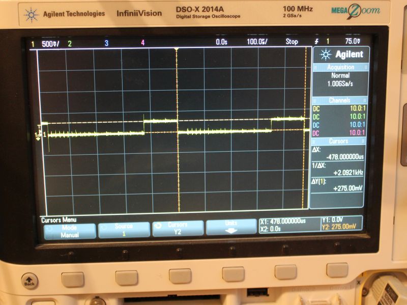
You can see 478us PWM-Period with a on-time of 126us. Thats a DutyCycle of 26% at 100% brightness. That explains the AC current measured earlier. The peak current is ~275mA.
- Red: 780mA, DutyCycle 17us/318us -> 0.5Watt RMS
- Green: 350mA, DutyCycle 108us/480us -> 0.95 Watt RMS
- Blue: 275mA, DutyCycle 126us/480us -> 0.86 Watt RMS
- White: 487mA, DutyCycle 98us/480us -> 1.19 Watt RMS
This roughly correlates with the 4Watts measured with the multimeter.
But what about the overall quality? I guess you get what you pay for.
- The LED PCB is made out of aluminium and is a decent heatsink. But it is rather thin. The LED-lenses are as described and work properly.
- Plastic case seems nice. No problems here
- The Control-Knobs are easy to use, the 7-Segment-Display shuts off after a few seconds. Premium feature!
- No gamma adjustment. 50% Brightness equals 50% (of max) DutyCycle.
- The DMX In- Out-Port are just connected to each other. No RS485-driver to improve signal quality
- The internal plugs are JST-XH (clones?), but they saved a few cents by just populating pins instead of complete receptables on the controller board.
- The PWM-Base-Frequency of red is different than the other colors. WTF?
- Since no DC is > 25% one would expect that the PWM-Periods are interleaved so the current does not add up. But nope, thats not the case.
- No resistors in front of the LEDs. So the 3 red LEDs which have a combined Vf lower than 9V are run at the full 12V.
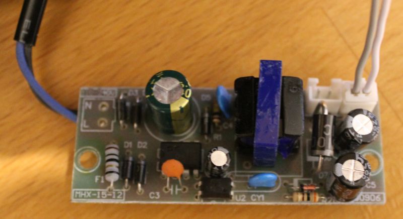
- There is no sign of any PFC on the primary side of the PSU.
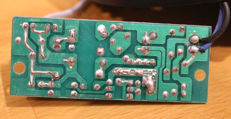
- The PSUs isolation between primary and secondary is garbage. The feedback-opto has all its 4 terminals pretty close to the primary side. Thats less than 1mm.
Conclusion – Next steps
So this is not as bright as I want it to be. And the PSU looks dangerous. So the next logical step is to fix that. I used a lab power-supply to check if each LED actually can handle 1Watt. The answer is yes, but then it gets hot rather quickly. So some sort of cooling is required.
I think the mod will be made with series-resistors in front of the LEDs so they can run of 12V DC. Then all 4 fixtures controlled by one KaratLight Device. Not sure about cooling yet, running this at 12Watt will be to much heat for the aluminium PCB to handle.
