El-cheapo China DMX LED Spots

I recently got me a set of 4 DMX-Controllable LED Lights of ebay for 35€ including shipping.

ebay-listing picture

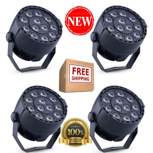
But they are rather dimm. The article page states

Power Consumption: 15W
LED: 12 pcs * 1W LED (Red*3, Green*3, Blue*3, White*3)

So, lets open one up and check the insides.insides of the led fixture, a multimeter

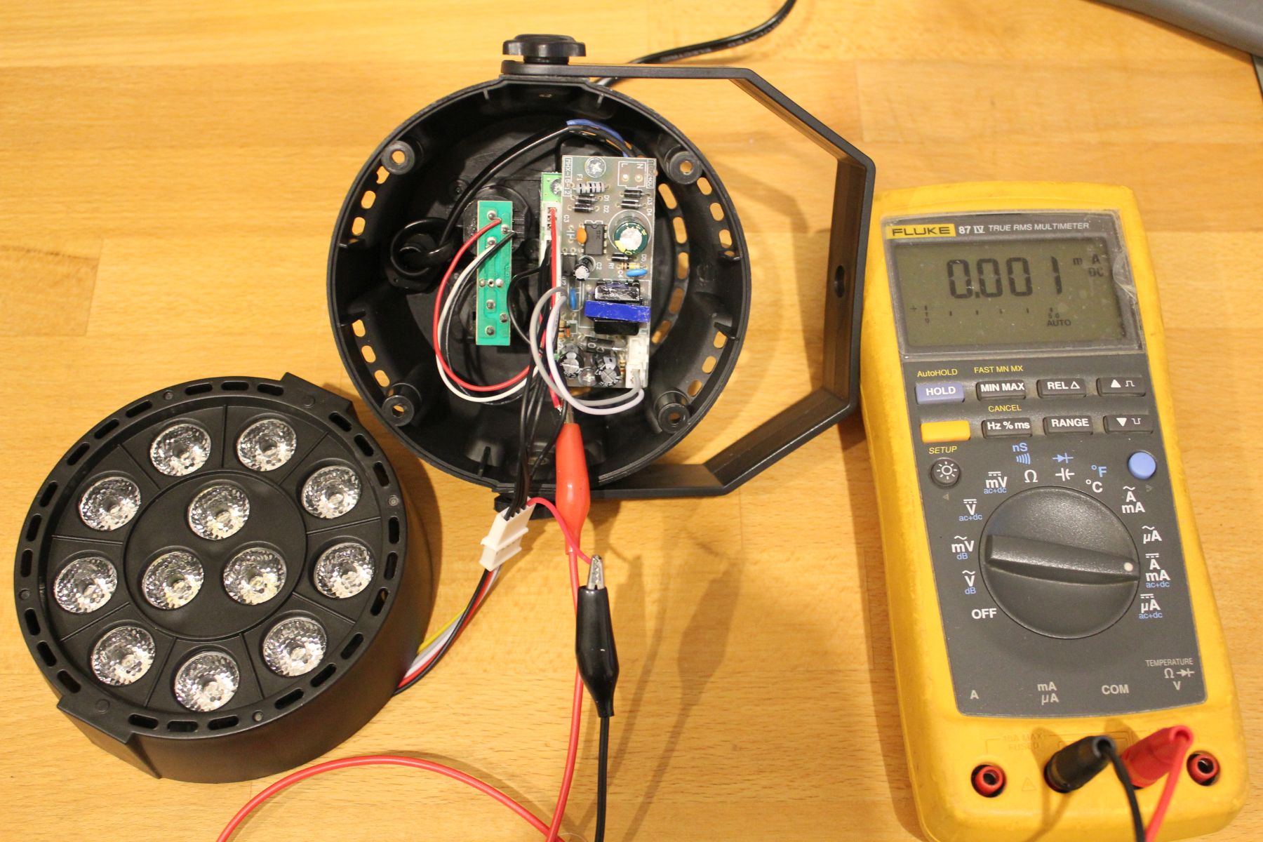
When setting all LEDs to maximum (RGBW) the multimeter reads 185mA DC. At just 12V thats not barely enough. Interestingly though, setting it to AC+DC mode reveals a stunning consumption of 340mA, thats almost 4Watt.

But wait, why is there even AC voltage when everything is turned up to full brightness?

Scope to the rescue!

I put a 1Ohm resistor in series to measure current, so 1mV -> 1mA. The voltage across the LEDs is always 12V, as output by the PSU.

scope showing the current waveform for the blue led

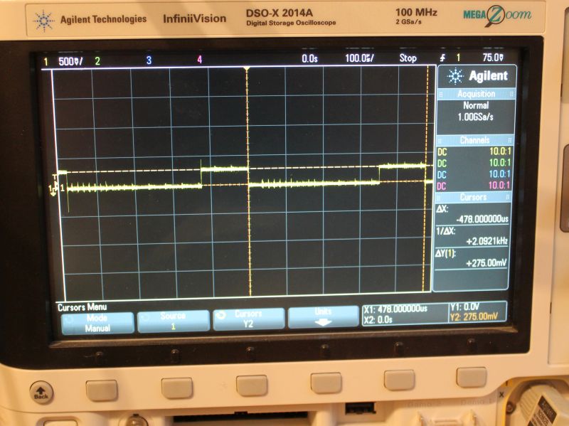
You can see 478us PWM-Period with a on-time of 126us. Thats a DutyCycle of 26% at 100% brightness. That explains the AC current measured earlier. The peak current is ~275mA.

  • Red: 780mA, DutyCycle 17us/318us -> 0.5Watt RMS
  • Green: 350mA, DutyCycle 108us/480us -> 0.95 Watt RMS
  • Blue: 275mA, DutyCycle 126us/480us -> 0.86 Watt RMS
  • White: 487mA, DutyCycle 98us/480us -> 1.19 Watt RMS

This roughly correlates with the 4Watts measured with the multimeter.

But what about the overall quality? I guess you get what you pay for.

  • The LED PCB is made out of aluminium and is a decent heatsink. But it is rather thin. The LED-lenses are as described and work properly.
  • Plastic case seems nice. No problems here
  • The Control-Knobs are easy to use, the 7-Segment-Display shuts off after a few seconds. Premium feature!
  • No gamma adjustment. 50% Brightness equals 50% (of max) DutyCycle.
  • The DMX In- Out-Port are just connected to each other. No RS485-driver to improve signal quality
  • The internal plugs are JST-XH (clones?), but they saved a few cents by just populating pins instead of complete receptables on the controller board.
  • The PWM-Base-Frequency of red is different than the other colors. WTF?
  • Since no DC is > 25% one would expect that the PWM-Periods are interleaved so the current does not add up. But nope, thats not the case.
  • No resistors in front of the LEDs. So the 3 red LEDs which have a combined Vf lower than 9V are run at the full 12V.
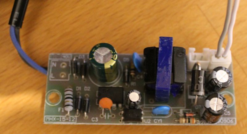
  • There is no sign of any PFC on the primary side of the PSU.
  • The PSUs isolation between primary and secondary is garbage. The feedback-opto has all its 4 terminals pretty close to the primary side. Thats less than 1mm.

Conclusion – Next steps

So this is not as bright as I want it to be. And the PSU looks dangerous. So the next logical step is to fix that. I used a lab power-supply to check if each LED actually can handle 1Watt. The answer is yes, but then it gets hot rather quickly. So some sort of cooling is required.

I think the mod will be made with series-resistors in front of the LEDs so they can run of 12V DC. Then all 4 fixtures controlled by one KaratLight Device. Not sure about cooling yet, running this at 12Watt will be to much heat for the aluminium PCB to handle.

Pizzaoven Reflow Soldering

Using a pizza oven for reflow soldering has already been done a million times by hackers/makers all over the world. You can even buy a ready made reflow controllers for such setups. Still, I will present my approach here since it is a little bit different from others I have seen so far.

Most setups use a relay to switch the heating element on/off. Some designs use a SSR and even have elaborate features like zero-crossing-detect. However, I didnt want to mess around with mains voltage. Thats why I decided to use a DMX512-Dimmer do control the heating element. When you think about it, its just another kind of lamp. So why not use a device made to control lamps?

The actual control is done with a Raspberry-Pi. I used a “max6667” Thermocouple amplifier from ebay which is interfaced via SPI. Fortunately there was enought sample code available on the net, I only had to do a litte copy&paste to get it running. I did modify the code to use the py-spidev library. My sourcecode is attached to this post. I also used python to run the PID-Temperature-Loop. Since that code is really ugly I wont publish it now  😀

Here is a picture of the complete Setup:

I did label some of the Items on the picture:

  1. Thermocouple
  2. max6667 board
  3. DMX Dimmerpack
  4. Raspberry Pi
  5. Temperature Monitor for Control/Debugging
  6. USB2DMX-Dongle

As mentioned above, a PID-Algorithm was used to control the temperature. The Profile is rather slow, but it does work. I might add insulation to the oven to allow faster heating.

Modified max6667-lib: max6667

A new USB2DMX based on PIC18F24K50 chip

I was in need of a cheap USB->DMX interface and decided to build my own. Searching the web I fould quite a lot DIY solutions. But most of them were unsuitable for me.

My design features:

  • low cost (about 10€)
  • open source: schematic and board are licensed CC-BY-NC-SA, the firmware is GPL (except microchip files)
  • a real rs485 transceiver
  • signal-generation by the Microcontroller (no bit-banging like the ftdi-dmx interfaces)
  • bootloader to update the firmware (thats what the switch is for – rescue mode)
  • fits into a ‘G027’ case (kemo-electronic)

If you take a look at the schematic you will see that the processor used is a 18F2550. But its possible and recommended to use the 18F24K50 which is cheaper and doesnt require a crystal oszillator. This is due to the fact that i made the initial design with the older controller (which i had at hand during the time).

On the software side there is a patch for ola. You will notice that reworked the ‘opendmx’ driver (i failed adding a new driver/directory to the build system).

There is no need to patch ola anymore. The karate-plugin is now in the mainline-tree.


Please respect the CC-BY-NC-SA licence when downloading and using it 🙂

20130506_kldmx_usb2dmx_Firmware

20130506_kldmx_usb2dmx_board