Ikea does sell a reasonably nice Ringlight called ‘LÅNESPELARE’. It runs of 5V and has a USB-A-Plug for its supply. A simple controller is build into the cord. Unfortunately, it does not remember its last setting/power status after it has been unplugged. If I switch it off via my home-automation using a zigbee outlet, I always need to also switch it on using its own controller. That kinda defeats the whole idea.
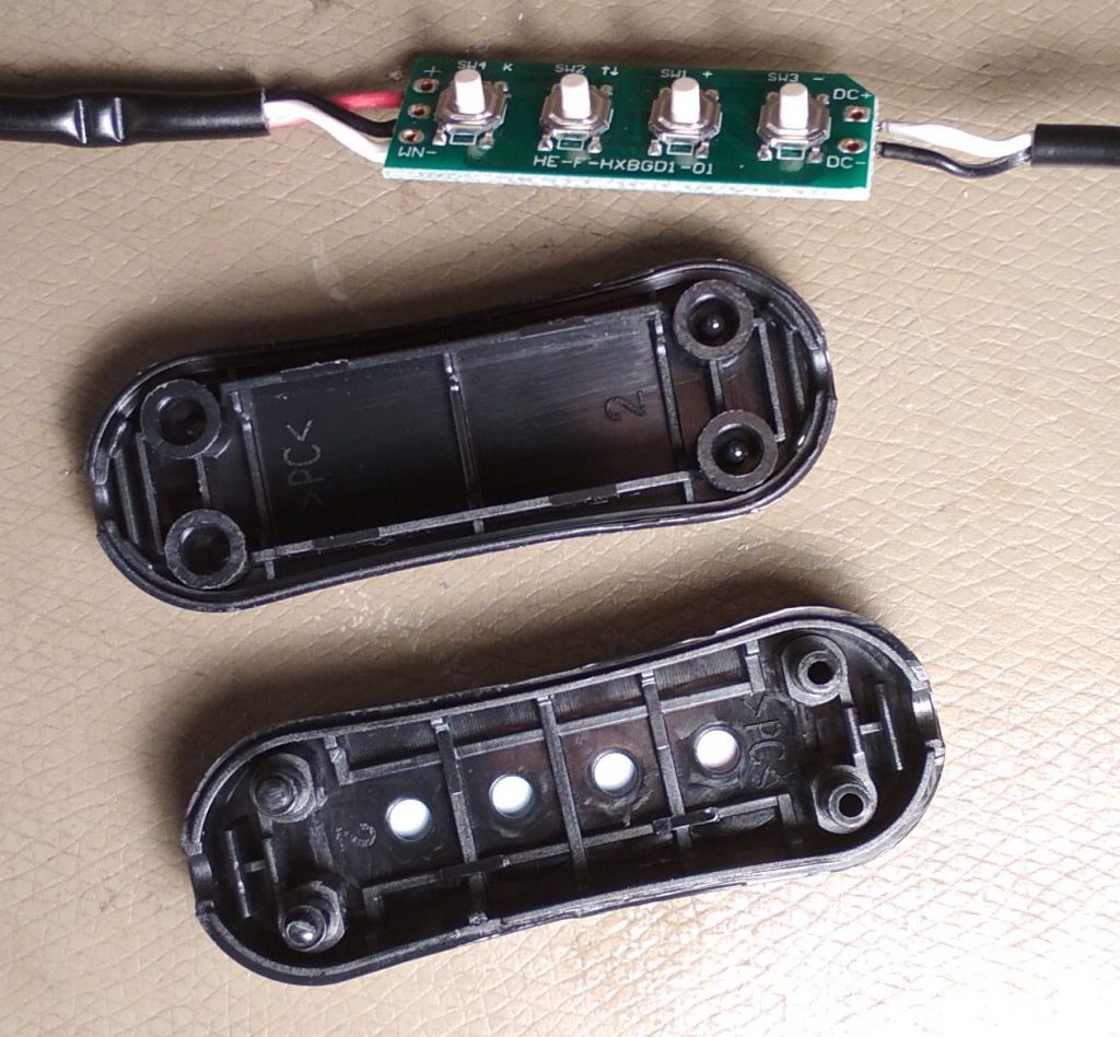
The case does not open that easy. I had to use some force, but managed to not break it. Perhaps the left domes have been welded, I heard a crack when I finally got it open.
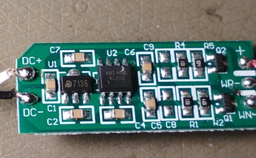
The original controller is pretty straightforward. It has a LDO (U1, “7136”, SOT-89 package) some kind of microcontoller (U2, SO-8 package), and two output transistors. One for Warmwhite and one for Coldwhite. The slikscreen reveals that those are low side switches. Seems like a simple PWM output.
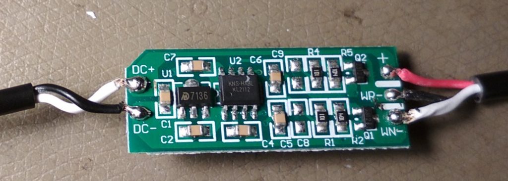
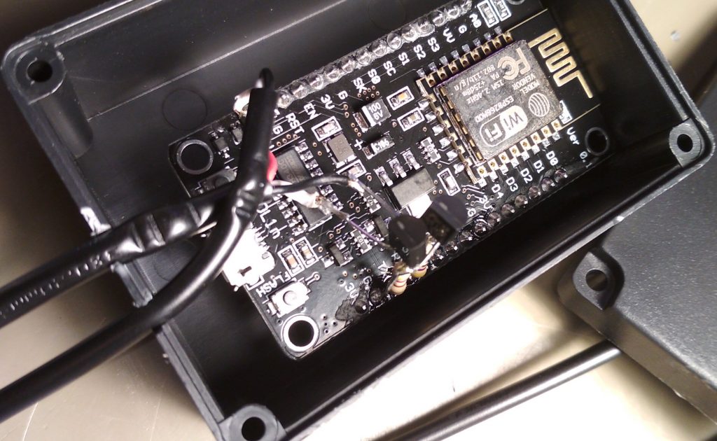
So we can replace it with another PWM controller. I choose to use https://github.com/Aircoookie/WLED since it integrates nicely into home-assistant. Its also really easy to configure and use. It already comes with a mode for PWM Output for warm/cold-white LEDs. All I had to do is to upload the firmware using esptool.py, no coding required at all. On the hardware-side two N-Channel-FETs (BS170) in TO-92 were used as low-side-switches. Then everything was fitted into a plastic case using excessive amounts of hot glue.
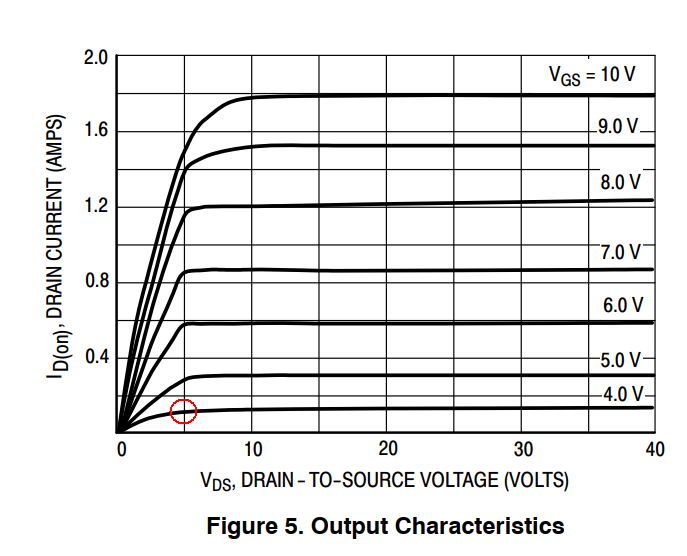
The BS170 is not the best FET for this application. Its Threshold-Voltage does not work well with the 3.3V of the esp8266. But those were the only available at the time. Below it the chart from its datasheet, with the working point circled in red. Perhaps I should just use the transistors from the original controller board 🙂
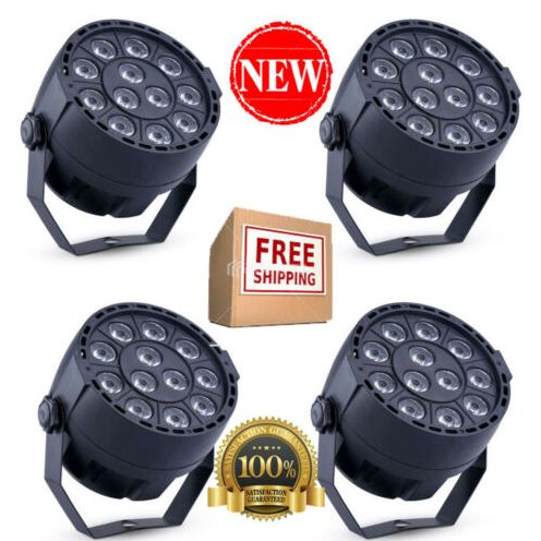
I recently got me a set of 4 DMX-Controllable LED Lights of ebay for 35€ including shipping.
ebay-listing picture
But they are rather dimm. The article page states
Power Consumption: 15W
LED: 12 pcs * 1W LED (Red*3, Green*3, Blue*3, White*3)
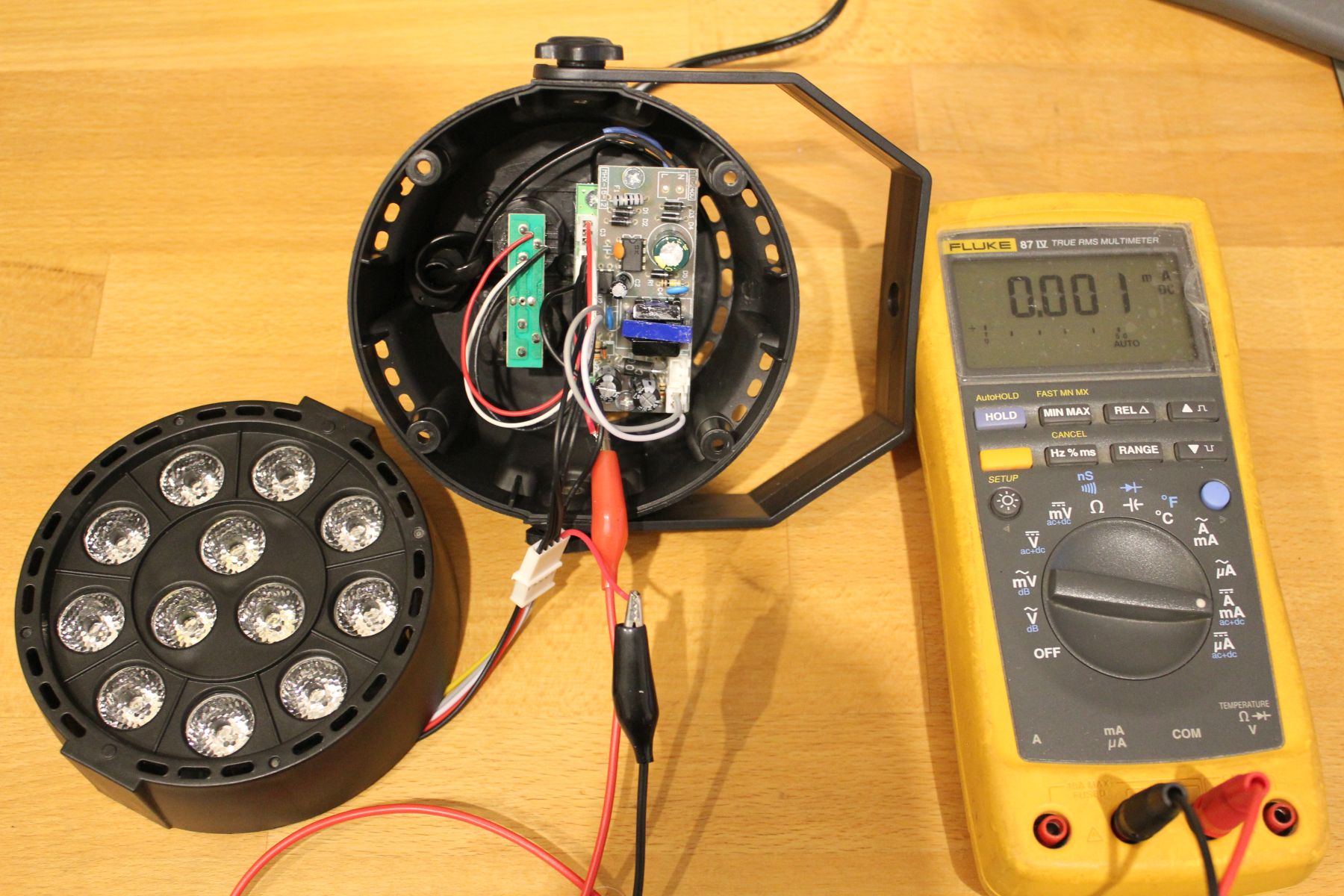
So, lets open one up and check the insides.
When setting all LEDs to maximum (RGBW) the multimeter reads 185mA DC. At just 12V thats not barely enough. Interestingly though, setting it to AC+DC mode reveals a stunning consumption of 340mA, thats almost 4Watt.
But wait, why is there even AC voltage when everything is turned up to full brightness?
Scope to the rescue!
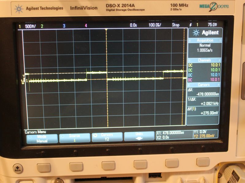
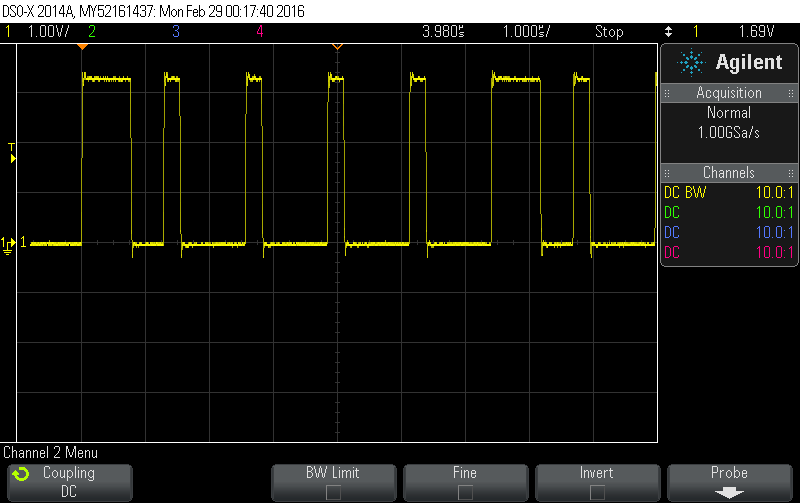
I put a 1Ohm resistor in series to measure current, so 1mV -> 1mA. The voltage across the LEDs is always 12V, as output by the PSU.
scope showing the current waveform for the blue led
You can see 478us PWM-Period with a on-time of 126us. Thats a DutyCycle of 26% at 100% brightness. That explains the AC current measured earlier. The peak current is ~275mA.
This roughly correlates with the 4Watts measured with the multimeter.
But what about the overall quality? I guess you get what you pay for.
The LED PCB is made out of aluminium and is a decent heatsink. But it is rather thin. The LED-lenses are as described and work properly.
Plastic case seems nice. No problems here
The Control-Knobs are easy to use, the 7-Segment-Display shuts off after a few seconds. Premium feature!
No gamma adjustment. 50% Brightness equals 50% (of max) DutyCycle.
The DMX In- Out-Port are just connected to each other. No RS485-driver to improve signal quality
The internal plugs are JST-XH (clones?), but they saved a few cents by just populating pins instead of complete receptables on the controller board.
The PWM-Base-Frequency of red is different than the other colors. WTF?
Since no DC is > 25% one would expect that the PWM-Periods are interleaved so the current does not add up. But nope, thats not the case.
No resistors in front of the LEDs. So the 3 red LEDs which have a combined Vf lower than 9V are run at the full 12V.
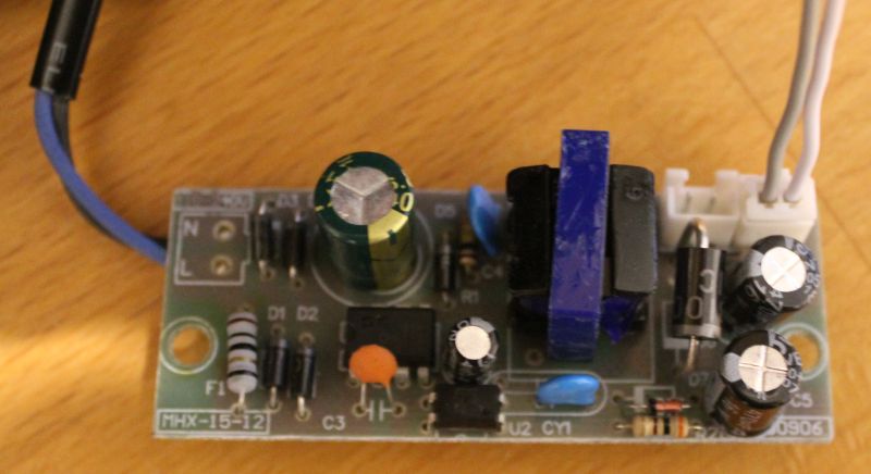
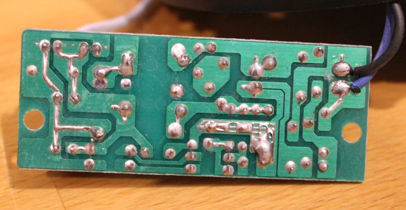
There is no sign of any PFC on the primary side of the PSU.
The PSUs isolation between primary and secondary is garbage. The feedback-opto has all its 4 terminals pretty close to the primary side. Thats less than 1mm.
12V PSU
Conclusion – Next steps
So this is not as bright as I want it to be. And the PSU looks dangerous. So the next logical step is to fix that. I used a lab power-supply to check if each LED actually can handle 1Watt. The answer is yes, but then it gets hot rather quickly. So some sort of cooling is required.
I think the mod will be made with series-resistors in front of the LEDs so they can run of 12V DC. Then all 4 fixtures controlled by one KaratLight Device. Not sure about cooling yet, running this at 12Watt will be to much heat for the aluminium PCB to handle.
Controlling WS2812 LED-Pixels from an Raspberry-Pi can be done. Other people have done this before: https://github.com/jazzycamel/ws28128-rpi/
My approach is different, but not that new either. I already implemented similar code for the Lightpainting-Stick-Clone.
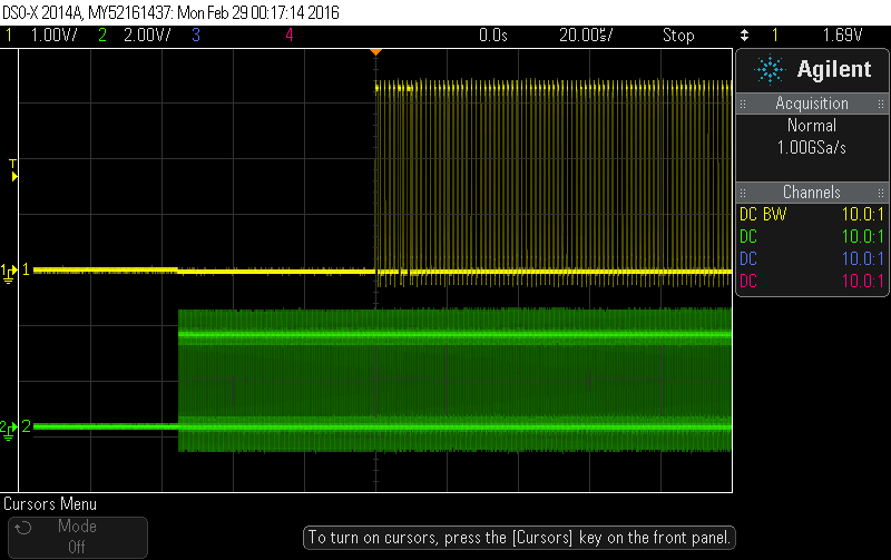
To get the required timing with the SPI we can output some patterns to make it look like the WS2812-Protocol.
The yellow line is MOSI (DIN). The 50us Reset is visible on channel 2.
Closeup of the actual timing. This image shows the first 7 bits (1000010)
However, there are some issues as metioned in the inline-comments. At first it seems like the code does not work when sending dmx-data with ola_dmxconsole. Once there are more changes in a short period of time, the pixels start to react. My guess here that this is related to the scheduler of the kernel. When as the kernel switches tasks the SPI output-stream gets interrupted, thus making the timing invalid. I will investigate this further.
void SPIOutput::IndividualWS2812Control(const DmxBuffer &buffer) {
  /*
   * This is an hack!
   *
   * Basically the RaspberryPI cant drive WS2812 Pixels because they have
   * some strict timing requirements.
   * Using the SPI-Module we can emulate those pulses.
   * This will only work if the SPI-Module outputs all data in one consecutive
   * stream without any pauses. More recent versions of the Raspberry Kernel
   * seem to implement DMA for SPI which makes this possible.
   *
   * WS2811-Chips have similar timings but not exactly the same as WS2812.
   * Some sources say the most important part is the total period-time
   * of one bit. There are lots of descriptions of WS2812-timing requirements
   * out there, one of them is: (with +-150ns tolerance)
   * 0-Bit 0.25us high, 1us low
   * 1-Bit 0.6us high, 0.65us low
   *
   * Running the SPI at 4Mhz gives us a pulse-width of 250ns
   * Using a 5-bit pattern we can emulate those timings
   *   0-Bit: 10000 (0.25us high, 1us low)
   *   1-Bit: 11110 (1us high, 0.25us low)
   * Those values are not an exact match, but they seem to work for both
   * WS2812 and WS2811 in high-speed-mode.
   *
   * We need to send 8 of those 5-packs for each byte. Those 40 bits are
   * precalculated and stored in a lookup table.
   *
   * To issue an reset, the data-line needs to be low for 50us, thats
   * 200 bits, or 25 bytes. For safety, we will send 27 bytes.
   *
   * Connect the Data-In-Pin of the LEDs to the MOSI Pin of the SPI-Module,
   * ignore the clock Pin.
   *
   */
  const uint8_t reset_bytes = 27;
  const unsigned int first_slot = m_start_address - 1;  // 0 offset
  // We always check out the entire string length, even if we only have data
  // for part of it
  const unsigned int output_len = reset_bytes + m_pixel_count *
                                  WS2812_SLOTS_PER_PIXEL * WS2812_SPI_LUT_LEN;
  uint8_t *output = m_backend->Checkout(m_output_number, output_len, 0);

  if (!output)
    return;

  // set the reset-bytes to zero
  memset(output, 0, reset_bytes);

  // loop over all pixels
  unsigned int output_pos = reset_bytes;
  for (uint16_t px = 0; px < m_pixel_count * WS2812_SLOTS_PER_PIXEL; px++) {
    uint8_t c = buffer.Get(px + first_slot);
    // now output 5 bytes from the LUT
    for (unsigned int lut = 0; lut < WS2812_SPI_LUT_LEN; lut++) {       output[output_pos++] = WS2812_SPI_LUT[c * 5 + lut];     }   }   m_backend->Commit(m_output_number);
}
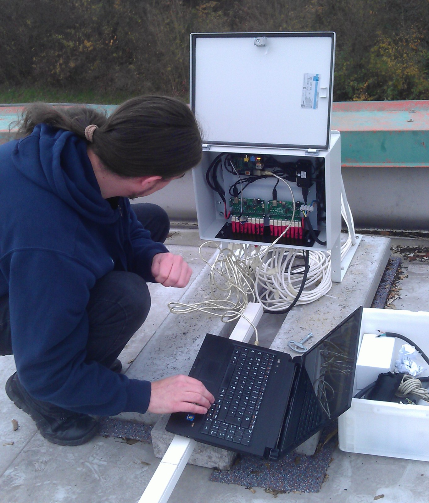
Earlier this year my colleague Rüdiger and me build some LED-Letters and mounted them to the building front. The letters themselfes are made of 20mm Acrylic with buildin RGB-LEDs. A 3mm black Acrylic plate was added on top to cover the LEDs and generate more contrast for daylight conditions.
This is actually me working. A rare picture 😀
The control is build around the OLA Software. A Raspberry-Pi drives all the components. Two KarateLight devices provide 8 RGB channels each. A USB-Hub (which also poweres the Pi) and a USB-WLAN-Stick make the setup complete. The LEDs are powered by two 320Watt switching-mode PSU. Everyhting fits nicely into a steel cabinet which makes this thing waterproof. In order to organize the cables coming in at the bottom I build two combs which clamp the cables into place.
Since i dont have a cool DMX Application i wrote a few lines of python to generate a simple animation. Basically all it does is calculate a gauss-distribusion which is then shifted from left to right. Its quite simple and not well implemented, but it works: ola.python_fader.
I then use ola_recorder to store a single run of the script into a file. Playback is also done with ola_recorder running inside screen.
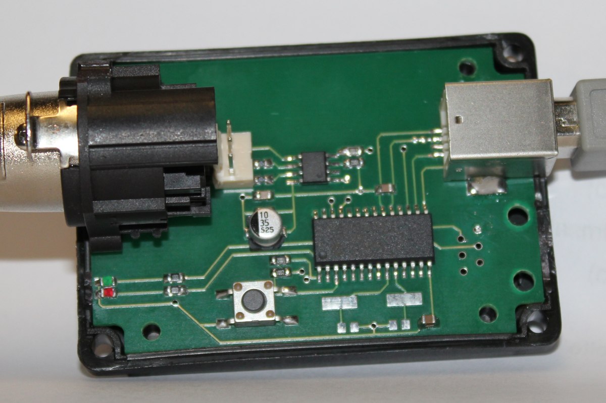
I was in need of a cheap USB->DMX interface and decided to build my own. Searching the web I fould quite a lot DIY solutions. But most of them were unsuitable for me.
My design features:
low cost (about 10€)
open source: schematic and board are licensed CC-BY-NC-SA, the firmware is GPL (except microchip files)
a real rs485 transceiver
signal-generation by the Microcontroller (no bit-banging like the ftdi-dmx interfaces)
bootloader to update the firmware (thats what the switch is for – rescue mode)
fits into a ‘G027’ case (kemo-electronic)
If you take a look at the schematic you will see that the processor used is a 18F2550. But its possible and recommended to use the 18F24K50 which is cheaper and doesnt require a crystal oszillator. This is due to the fact that i made the initial design with the older controller (which i had at hand during the time).
On the software side there is a patch for ola. You will notice that reworked the ‘opendmx’ driver (i failed adding a new driver/directory to the build system).
There is no need to patch ola anymore. The karate-plugin is now in the mainline-tree.
Please respect the CC-BY-NC-SA licence when downloading and using it 🙂