A new USB2DMX based on PIC18F24K50 chip

I was in need of a cheap USB->DMX interface and decided to build my own. Searching the web I fould quite a lot DIY solutions. But most of them were unsuitable for me.

My design features:

  • low cost (about 10€)
  • open source: schematic and board are licensed CC-BY-NC-SA, the firmware is GPL (except microchip files)
  • a real rs485 transceiver
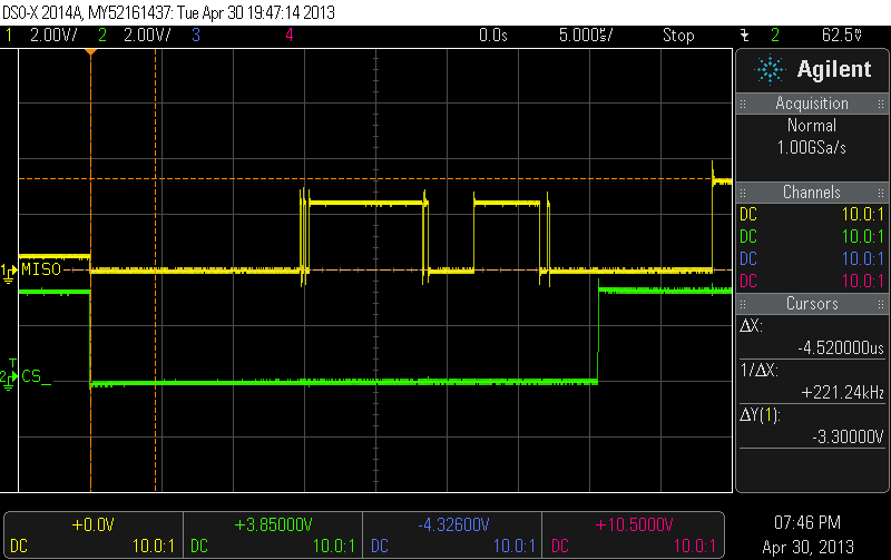
  • signal-generation by the Microcontroller (no bit-banging like the ftdi-dmx interfaces)
  • bootloader to update the firmware (thats what the switch is for – rescue mode)
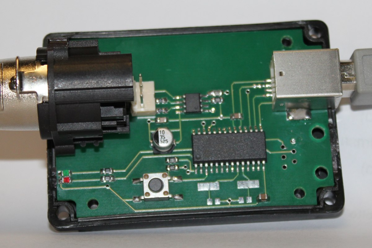
  • fits into a ‘G027’ case (kemo-electronic)

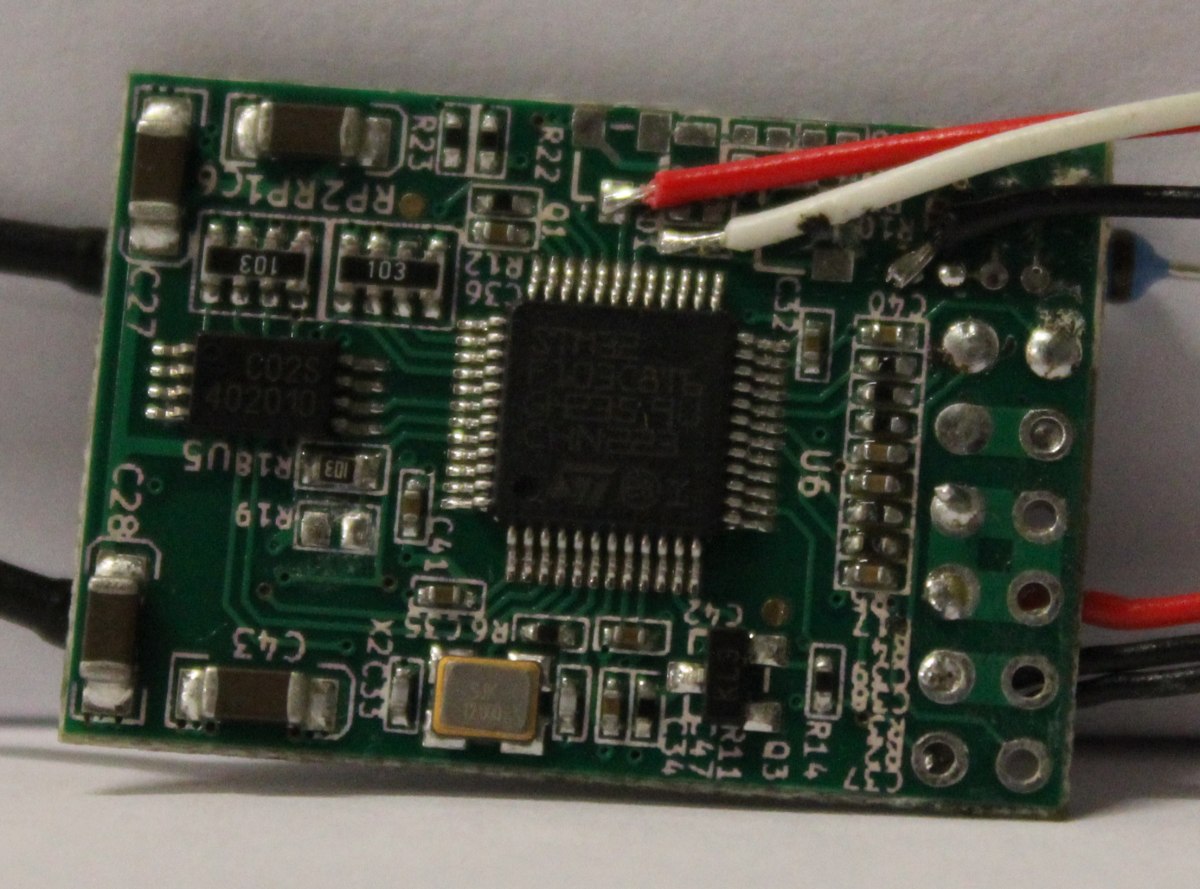
If you take a look at the schematic you will see that the processor used is a 18F2550. But its possible and recommended to use the 18F24K50 which is cheaper and doesnt require a crystal oszillator. This is due to the fact that i made the initial design with the older controller (which i had at hand during the time).

On the software side there is a patch for ola. You will notice that reworked the ‘opendmx’ driver (i failed adding a new driver/directory to the build system).

There is no need to patch ola anymore. The karate-plugin is now in the mainline-tree.


Please respect the CC-BY-NC-SA licence when downloading and using it 🙂

20130506_kldmx_usb2dmx_Firmware

20130506_kldmx_usb2dmx_board

Reworking a FrSky D4R-II Receiver

Since i want to use telemetry with my soon-to-be-finished uavp-ng quadcopter i decided to use a FrSky two-way-telemetry system. Unfortunately the enigneers at FrSky choose to invert the serial signal which wont work on the hw0.24-mini.

Thats why i took a closer look at the receiver pcb. Fortunately it was quite easy to identify the UART-Pins with TTL levels. I removed the two transistors and some resistors which arent needed anymore.

The pinheader was also removed in this process. I added a bridge on ch3&4 to active CPPM-mode.

As a additional modification  a voltage divider was installed. The AD2-Input of the receiver works up to 3.3Volt. With a 3k3 and a 10k resitor i was able to build a network with a convenient 1:4 scale factor. With 4*3.3Volt > 13V i can monitor the voltage of a 3S LiPo 🙂

Building a quadcopter – Electronics

This is how my Workspace looks after a few hours of debugging 🙂

I did some work on quadcopter-frames in the past, so inspired by the NG-UAVP-Project i decided to build my own quadcopter.

Since those guys offer blank PCBs i ordered some and build a Flight-Controller (hw0.24-mini-r2) and a Quad-Brushless-Controller (ngblc-r2). After some trouble with customs/taxes and missing parts i was finally able to assemble and test both boards. As always not everything works out of the box (soldering errors, missing parts, …).

  • Make sure to populate R68/R69. Those are current-limiting resistors for the backup battery for the Venus-GPS and the RTC. I left them open in the first place sind i didnt populate the battery. However, the Venus-GPS needs power at the Vbat-Pin to work. I spend about 3 hours searching for errors in the serial-communication :/
  • Check the supply voltages of each chip. The coil in the the LC-Filter for the MPU-Accellerometer was broken; however the MPU somehow still worked (eg got some supply current over clamping diodes), but did not answer SPI-requests correctly.
  • Cabeling is also an issue. The picoblade connectors are nice and small, but sometimes dont give good contact. I had some issues with the external-i2c-sensor bus because one pin didnt provide good contact.

There are still some open issues:

  • The LIS3L-Accelerometer wont get recognized on the SPI-Bus
  • On the ngblc there seems to be at least on misplaced part. On of the supply-voltages drops down because of overcurrent. I am still investigating this.


As next steps i will finish the mechanical setup. Mount the motors to the frame and do some wiring.