Fix broken pins on QFP Package

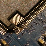
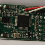
That is how my new HW-0.30-mini Quadcopter Flightcontrol looked prior to the repair:

broken pins

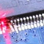
Since a few of the Pads already were delaminated I decided to do a repair instead of soldering in a new CPU. For a repair I would need to get rid of the expoxy mold to directly acces the pins of the leadframe. Initially I was thinking of using a ‘dreml’ tool to remove the exoxy, but watching the Uncaging Microchips talk at 31C3 taught me that using a CO2-Laser will also work.

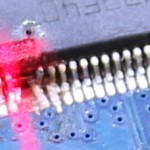
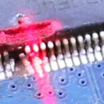
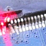
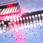
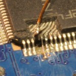
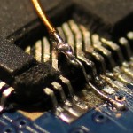
Those pictures were taken during the laser-removal:


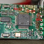
After lasering, all left to do was attach new wires. I did use a microscope for that. For scale, the wire running on top of the CPU has a 0.3mm diameter.

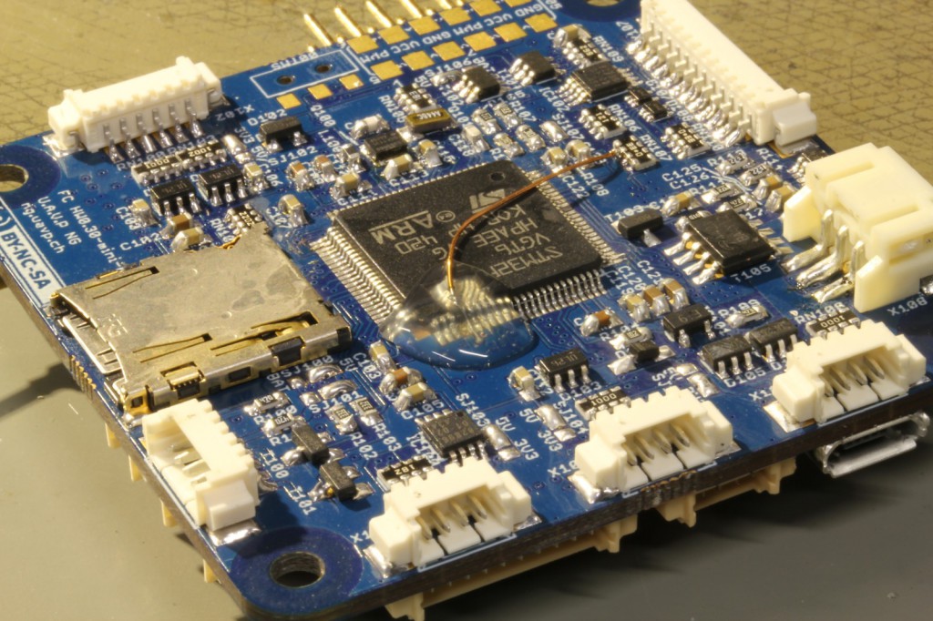
I ran some quick tests with the software to make sure the repair worked. Then a blob of hotmelt was applied to secure and protect the repaired pins:

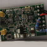
HW-0.30-mini fixed


Backstory: I am also responsible for breaking the pins. I did solder the CPU at 31C3 without proper lighting using borrowed equipment. The temperature on the soldering iron was set to 450°C, I failed to check that. This lead to some major fuckup. Since I wanted to work with the board, the decision was made to simply cut of the broken pins. At the time I didnt need them.
Reworking a FrSky D4R-II Receiver

Since i want to use telemetry with my soon-to-be-finished uavp-ng quadcopter i decided to use a FrSky two-way-telemetry system. Unfortunately the enigneers at FrSky choose to invert the serial signal which wont work on the hw0.24-mini.

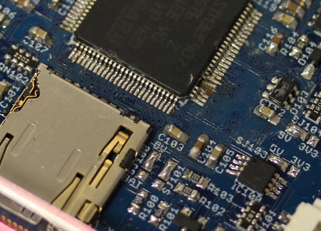
Thats why i took a closer look at the receiver pcb. Fortunately it was quite easy to identify the UART-Pins with TTL levels. I removed the two transistors and some resistors which arent needed anymore.

The pinheader was also removed in this process. I added a bridge on ch3&4 to active CPPM-mode.

As a additional modification  a voltage divider was installed. The AD2-Input of the receiver works up to 3.3Volt. With a 3k3 and a 10k resitor i was able to build a network with a convenient 1:4 scale factor. With 4*3.3Volt > 13V i can monitor the voltage of a 3S LiPo 🙂

Building a quadcopter – Electronics

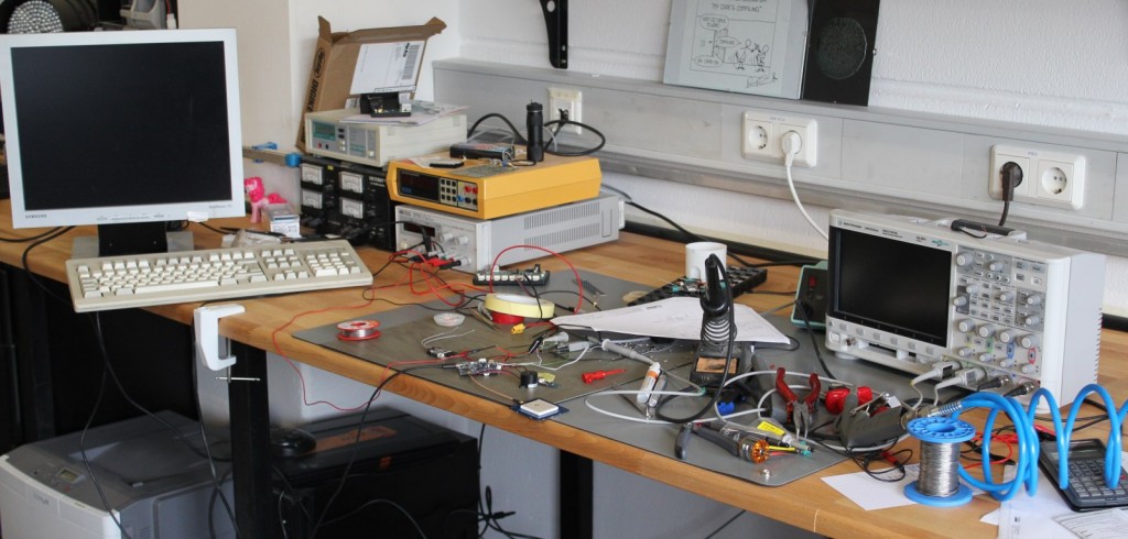
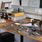
This is how my Workspace looks after a few hours of debugging 🙂

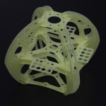
I did some work on quadcopter-frames in the past, so inspired by the NG-UAVP-Project i decided to build my own quadcopter.

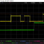
Since those guys offer blank PCBs i ordered some and build a Flight-Controller (hw0.24-mini-r2) and a Quad-Brushless-Controller (ngblc-r2). After some trouble with customs/taxes and missing parts i was finally able to assemble and test both boards. As always not everything works out of the box (soldering errors, missing parts, …).

  • Make sure to populate R68/R69. Those are current-limiting resistors for the backup battery for the Venus-GPS and the RTC. I left them open in the first place sind i didnt populate the battery. However, the Venus-GPS needs power at the Vbat-Pin to work. I spend about 3 hours searching for errors in the serial-communication :/
  • Check the supply voltages of each chip. The coil in the the LC-Filter for the MPU-Accellerometer was broken; however the MPU somehow still worked (eg got some supply current over clamping diodes), but did not answer SPI-requests correctly.
  • Cabeling is also an issue. The picoblade connectors are nice and small, but sometimes dont give good contact. I had some issues with the external-i2c-sensor bus because one pin didnt provide good contact.

There are still some open issues:

  • The LIS3L-Accelerometer wont get recognized on the SPI-Bus
  • On the ngblc there seems to be at least on misplaced part. On of the supply-voltages drops down because of overcurrent. I am still investigating this.


As next steps i will finish the mechanical setup. Mount the motors to the frame and do some wiring.