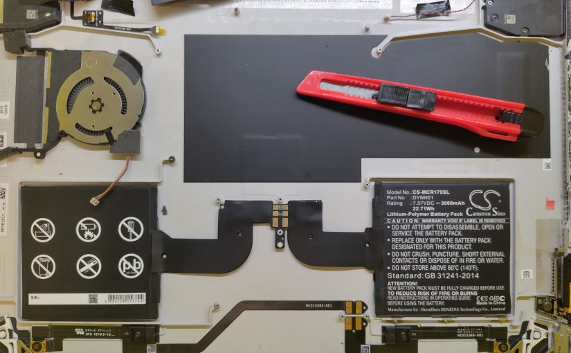
This is probably the worst repair I have recently helped with. This device has almost everything glued and horrible connector locations. The original goal was to replace the loud fan (watch the video with sound), and while we are at it, also put in a new battery and touchscreen.
My main pain-points were
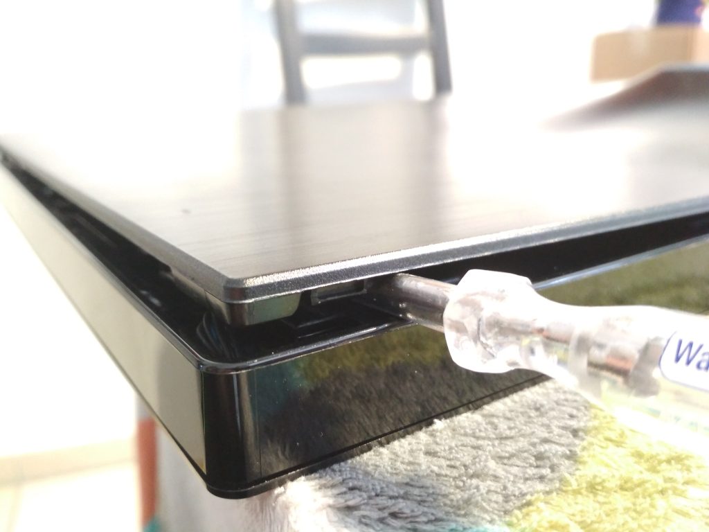
- glued in touchscreen + display assembly
- while removing it, I did destroy two antennas that are directly below the glue layer
- if you don’t want to make the same mistake, be really gentle on the top edge of the screen (where the cameras are)
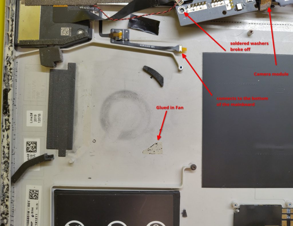
- two cameras glued in and need to be removed together with the mainboard
- the camera connector cannot be unplugged without removing the mainboard.
- the mainboard cannot be removed while the camera is glued in. catch22 of disassembly
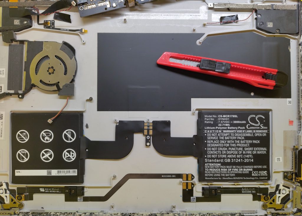
- battery pack glued in (I mean, we are already used to it, still shitty)
- fan glued in
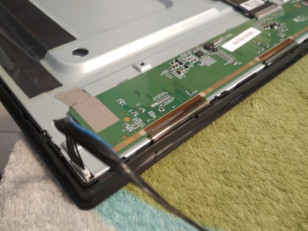
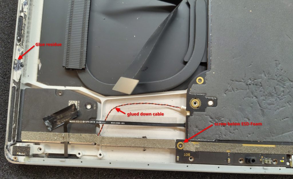
- wires inside fixed with tape (that is actually not that painful)
- screws hidden below ESD-foam
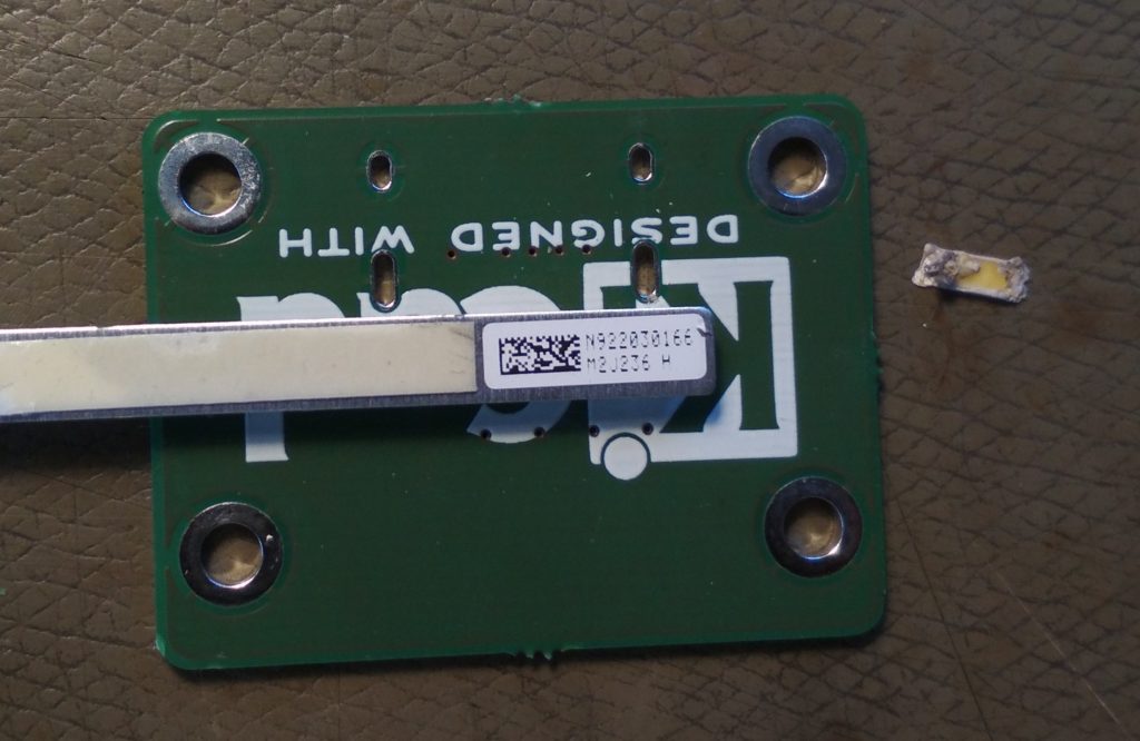
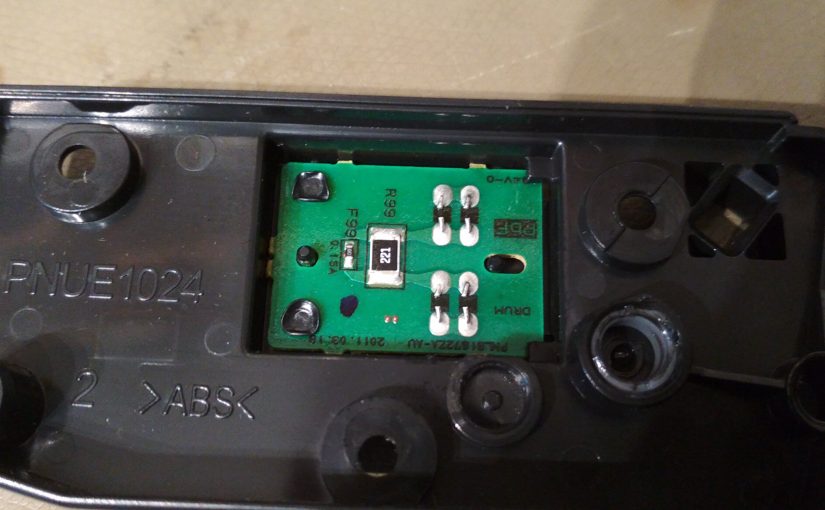
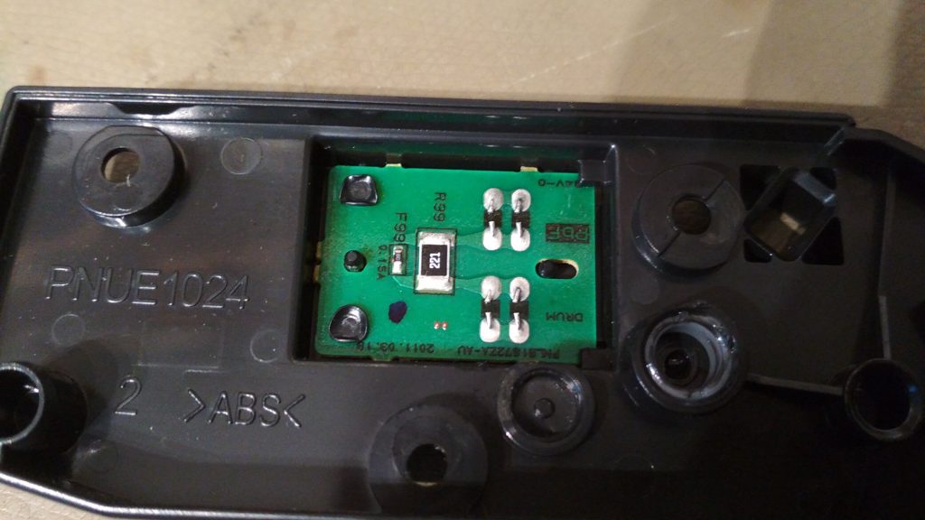
- touchscreen controller glued to the back of the screen
- and its important that the bottom of that PCB makes good contact with the case of the screen to have a reference for the capacitive sensing
- There was a conductive glue pad, but I had nothing to replace it
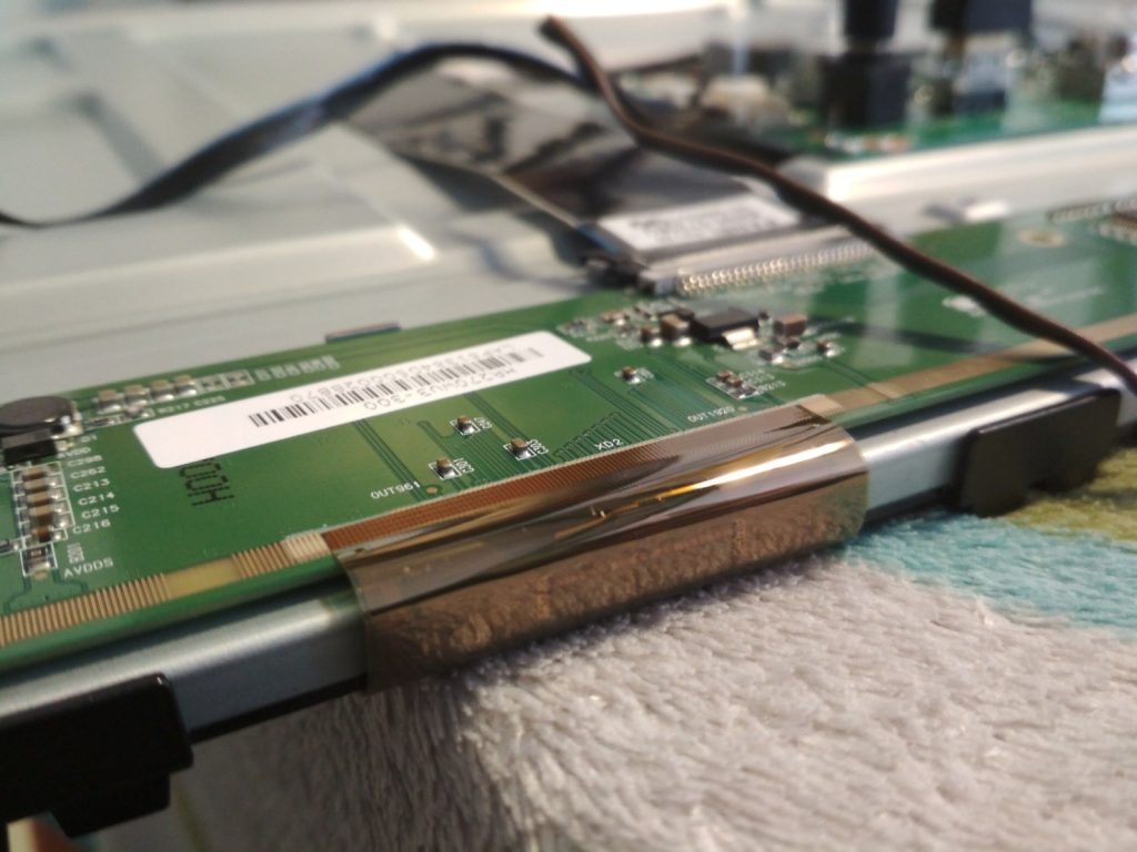
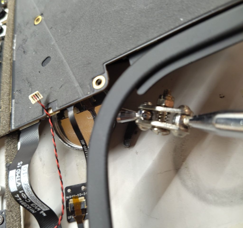
- more FPC connectors between the mainboard and the case
- which cannot reasonably be opened and closed for disassembly
- require a dentist mirror tweezers and magic to reassemble
- did I already say fucking glue everywhere?
- vendor part names and spare part numbers are confusing
I want to mention that iFixit does have a really useful page about the device https://www.ifixit.com/Guide/Microsoft+Surface+Book+2+15-Inch+Battery+Replacement/160660
Unfortunately, the images were not taken in the exact disassembly order. In the step “Detach the ribbon cables connecting the underside of the screen to the motherboard.” which is before the removal of the mainboard, the corresponding image already has the mainboard screws removed.
But that is complaining on a really high level, considering the guide even says “WARNING: This guide is missing many steps.”.
Having a 95% correct guide is still way more useful than having none at all. I am publishing those images in the hopes that they might help with your repair.
https://learn.microsoft.com/en-us/surface/surface-system-sku-reference, Surface_Book_1793