Turns out the drives of my Scara Robot are not velocity-mode drives but torque-mode drives instead. Setting the drive input to a constant voltage results in constant accelleration. I learned this the hard way by crashing the robot :-/
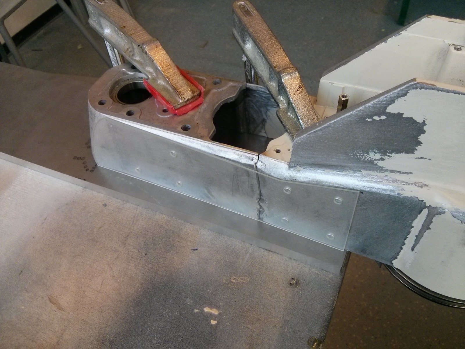
Even though I had it fixed on an Europalette it managed to fall on its side. Second lesson learned: even ‘small’ a 200W drive can turn the whole thing in a fraction of a second. Hitting the floor broke some pieces. But see for yourself:
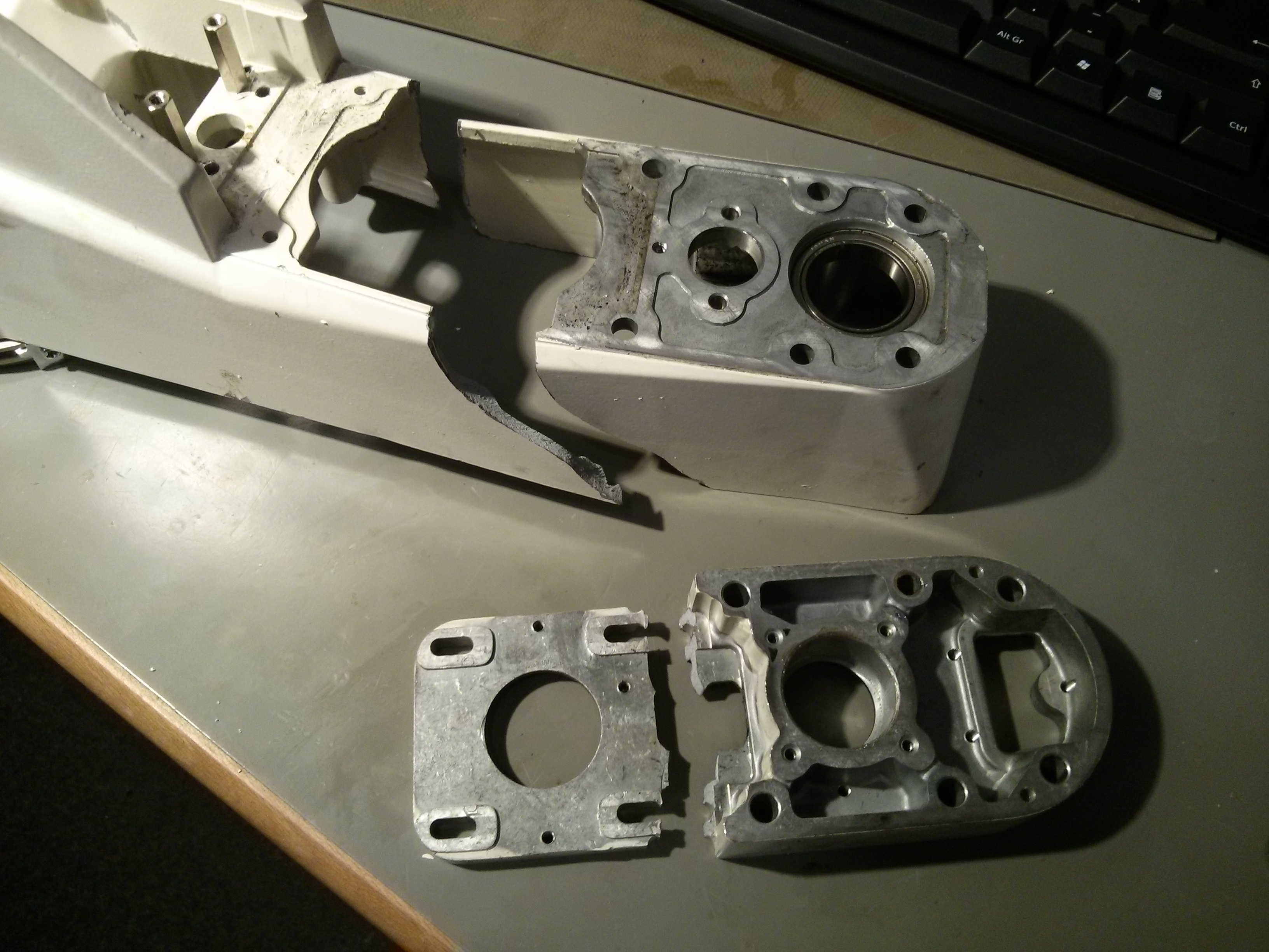
Those parts are both made out of cast aluminium. I do lack the equipment and skill to weld, so I asked a Friend of mine to do it. However, even with his long time experience he wasn’t able to fix the parts together. At first I got desperate and tried hard-soldering the Z-Motor-Mount. But even using two torches I wasnt able to get the part hot enough to accept the solder.
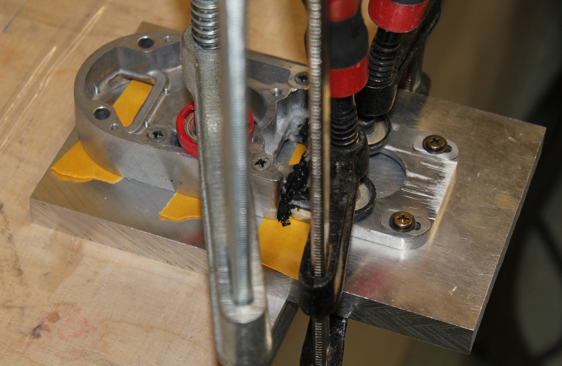
As a last resort I deceided to glue the parts. Fortunately my sister works as a postdoc and is an expert for aluminium epoxy bonds. She did some rought calculations for me and helped select the correct adhesive: 3M Scotch-Weld DP490.
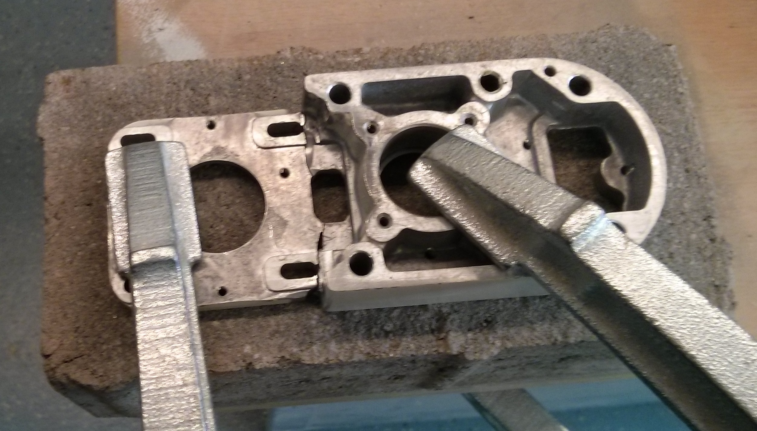
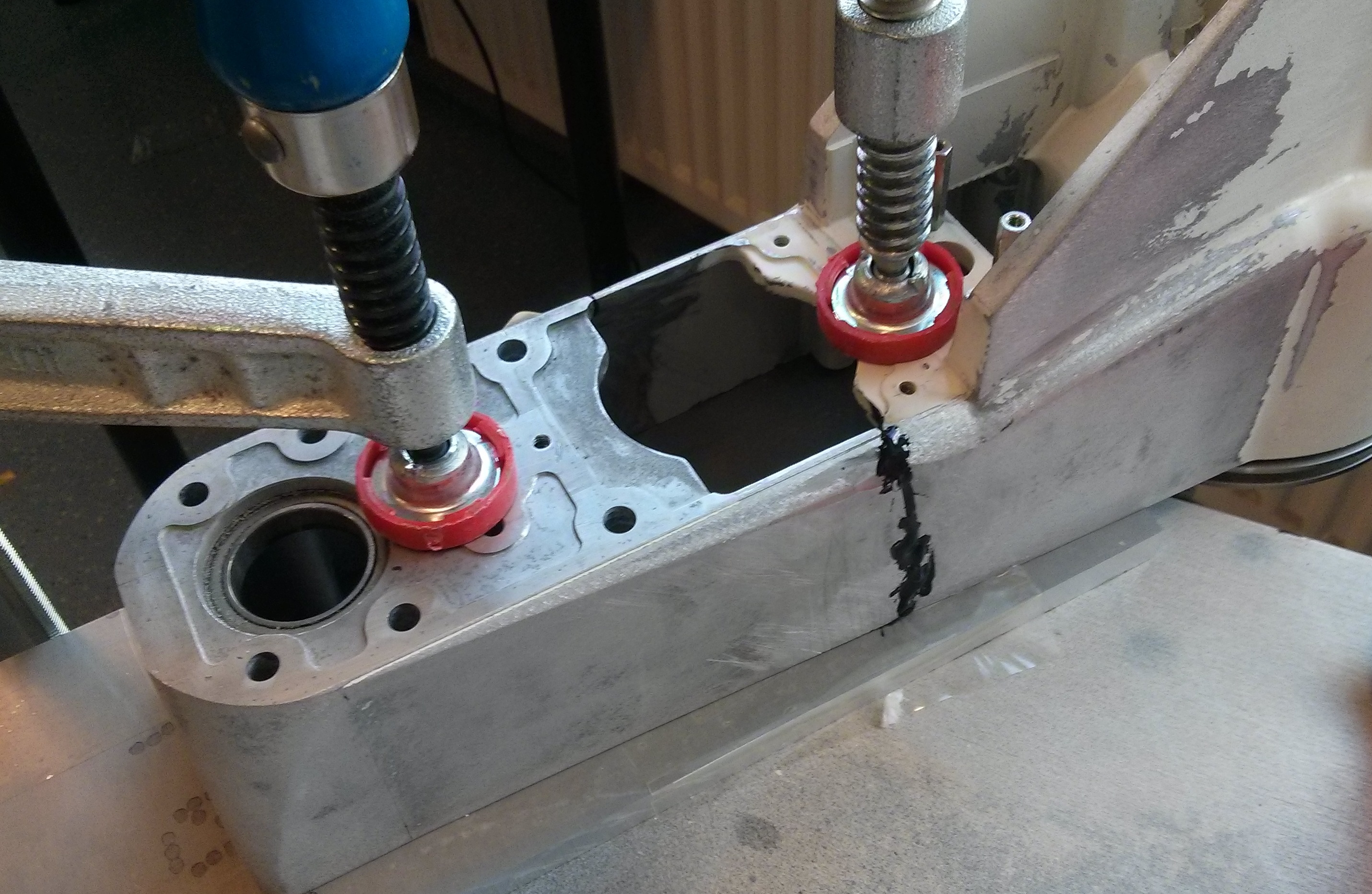
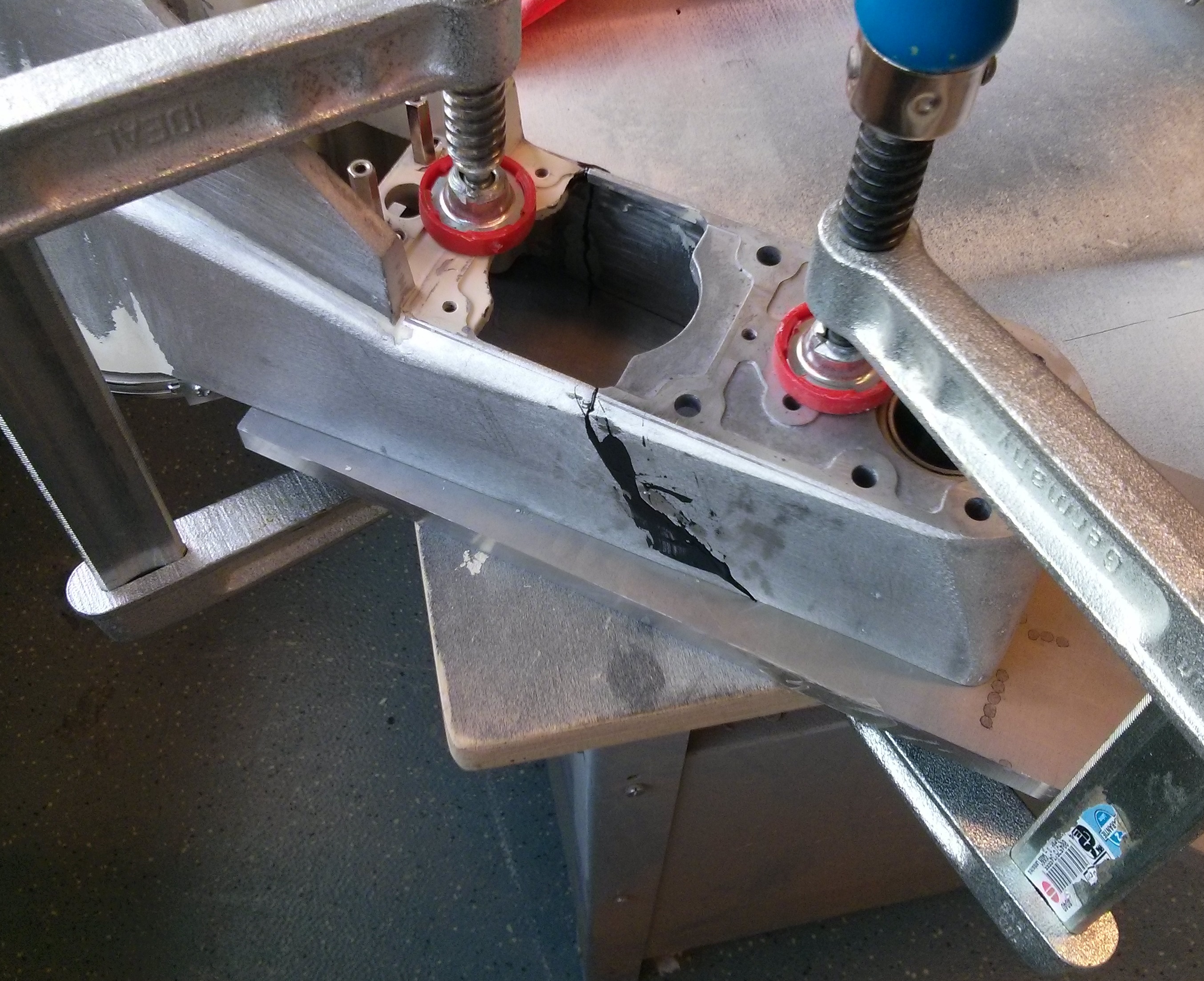
I prepared the parts by grinding away all paint and about 100microns of the aluminium. The last step helps because cast aluminium has different properties on the outer layers compared to the inner bulk material due to the casting process. I also cut some reinforcement plates from 6061 Aluminium. Then I cleaned everything several times with water/soap and acetone. Everything was clamped down on a clean plate and glued together in two steps: First the two broken bits were fixed together. After curing the residual glue was removed by grinding, then the reinforcement plates were glued. To improve the curing process I put a box over it to trap the air inside and heated everyhing which a hot air gun to 80°C. Unfortunately I didnt take that many pictures of the process:
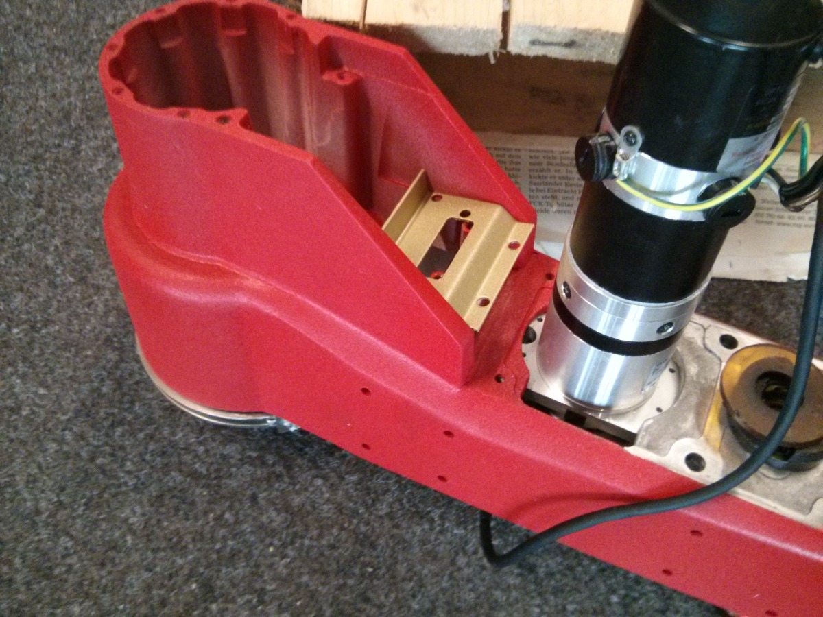
After that, I did some cosmetics. With a lot of car putty, grinding and even more putty and finally a red finish the part looked like this:
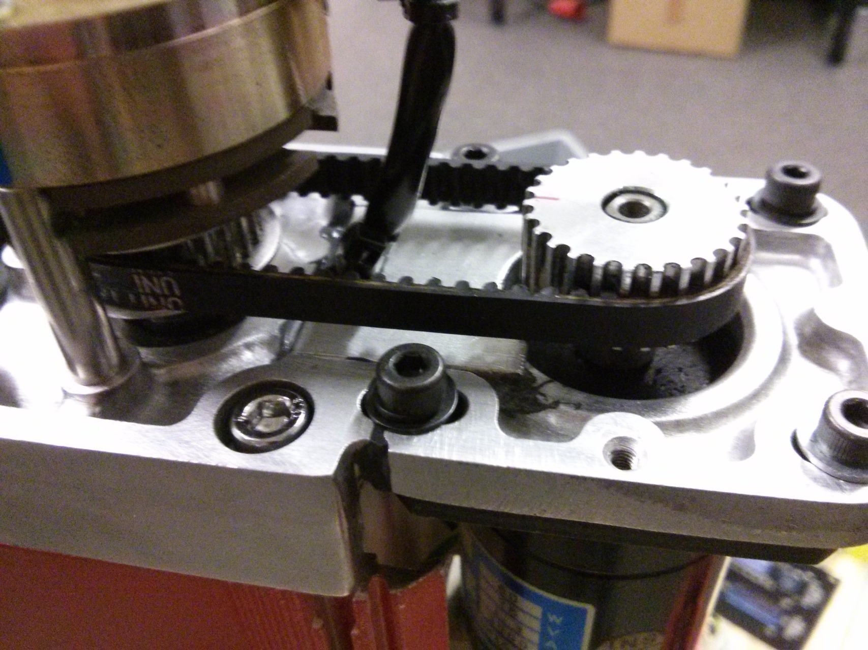
That concludes the B-Arm. Fixing the Z-Motor-Plate was basically the same. Here are some more pictures:
That concludes the repair. I will cover the mechanical and electrical rebuild in a seperate Blogpost.