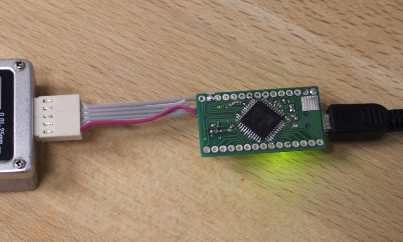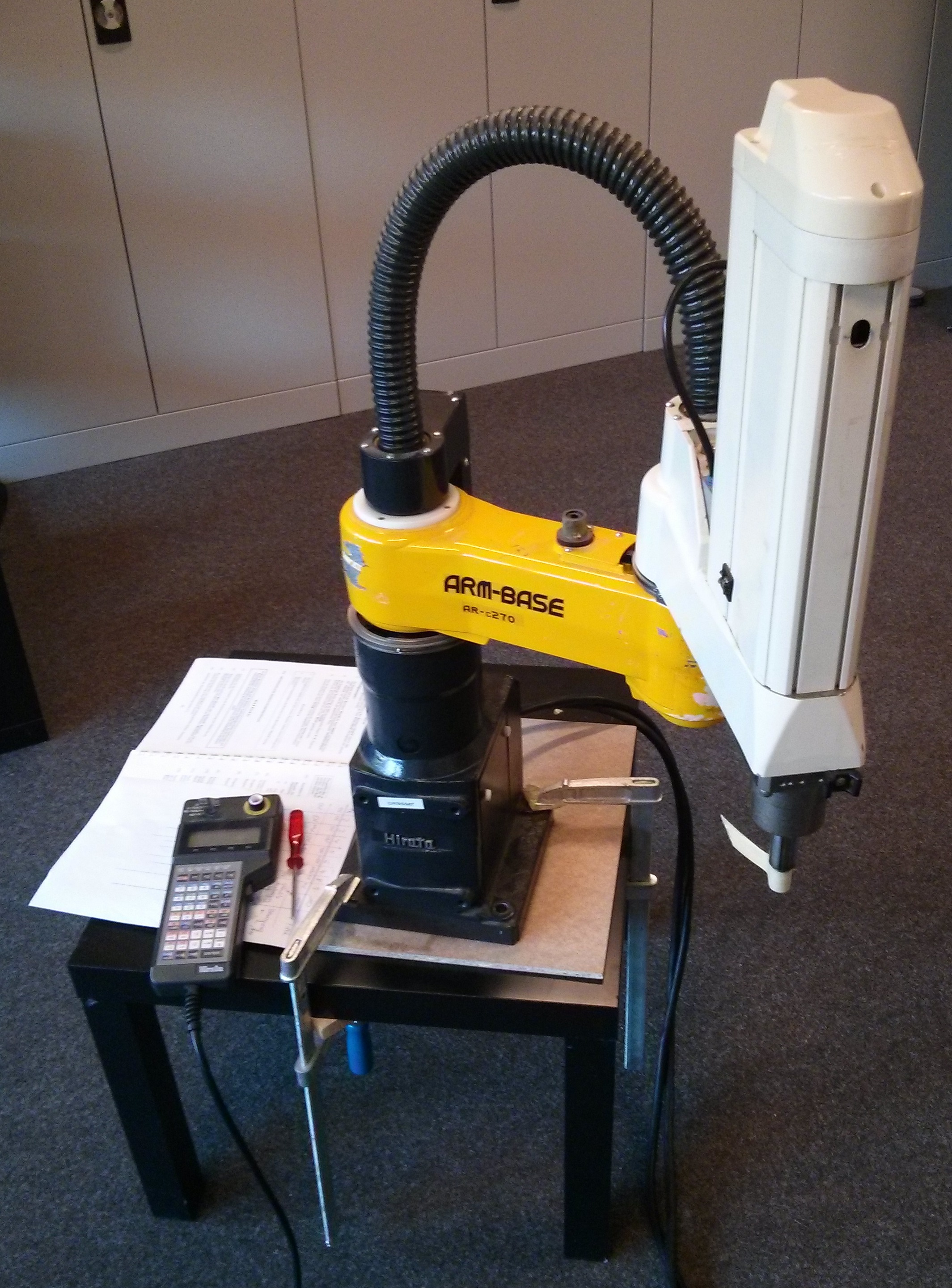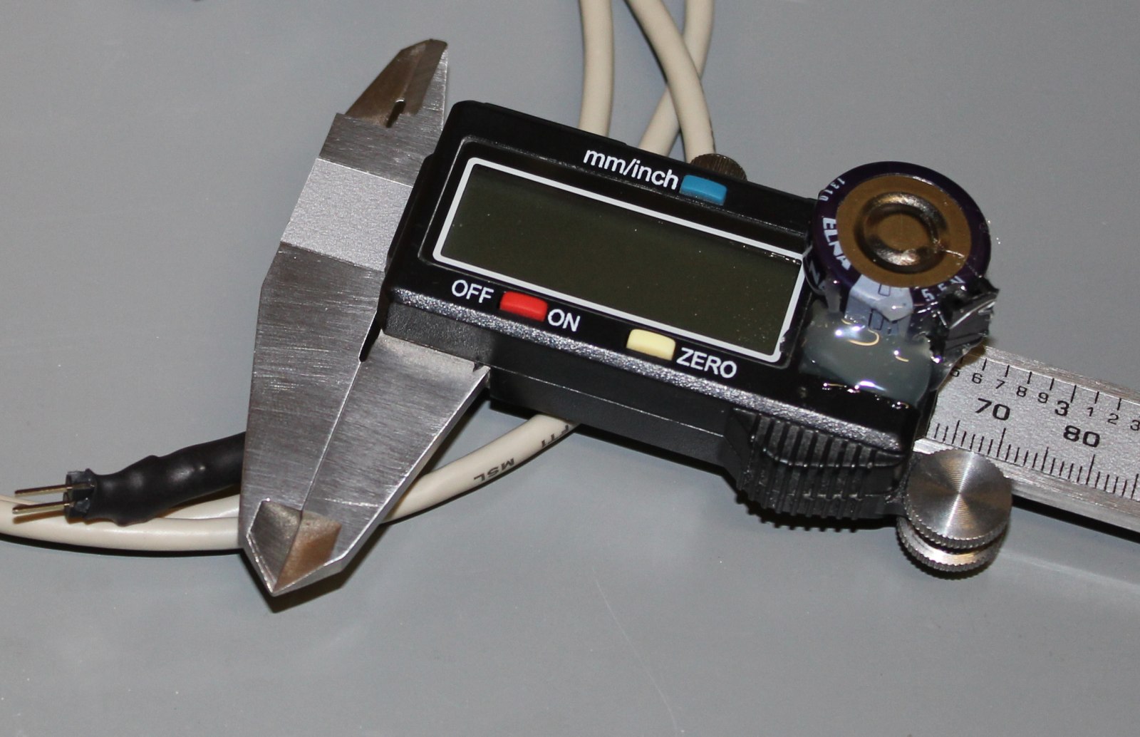
A few years ago I bought some Battery indicators on Aliexpress. They are sold for different battery configurations, mine says 13.2..16.8V, so its most likely for 4S LiPo. The part apparently is called XW228DKFR4.
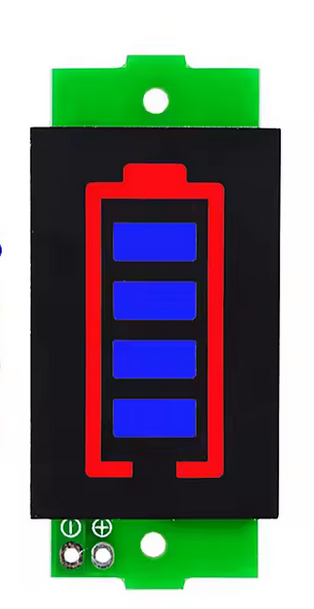
But now I have a 8S LiFePo pack and want to modify it to match its voltage. LiFePo has a rather flat voltage over its state-of-charge, so most likely this will not work well. But it sure is better than no indicator. So I took a closer look so I can change the circuit to work with about double the voltage.
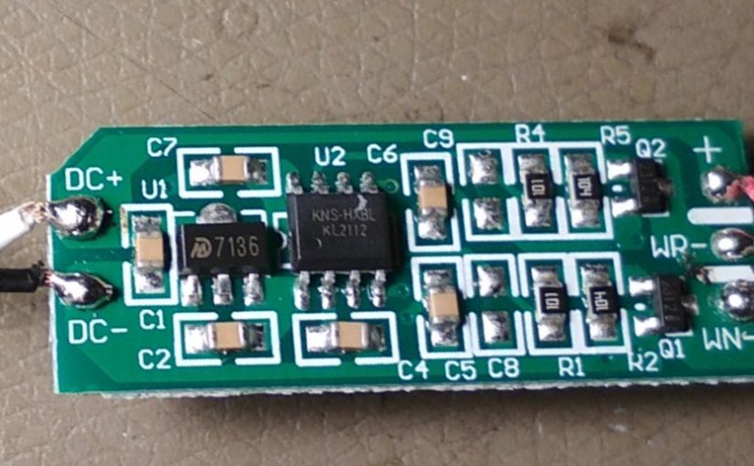
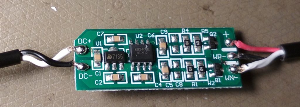
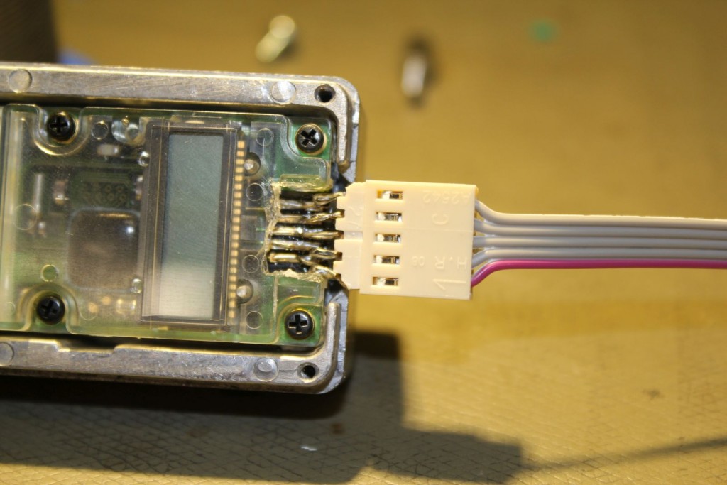
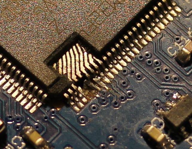
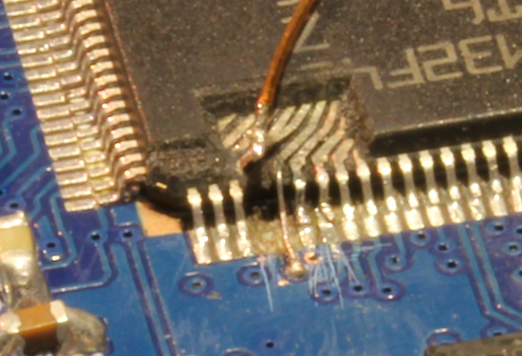
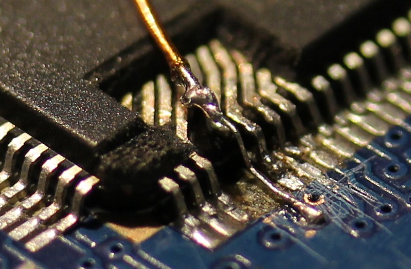
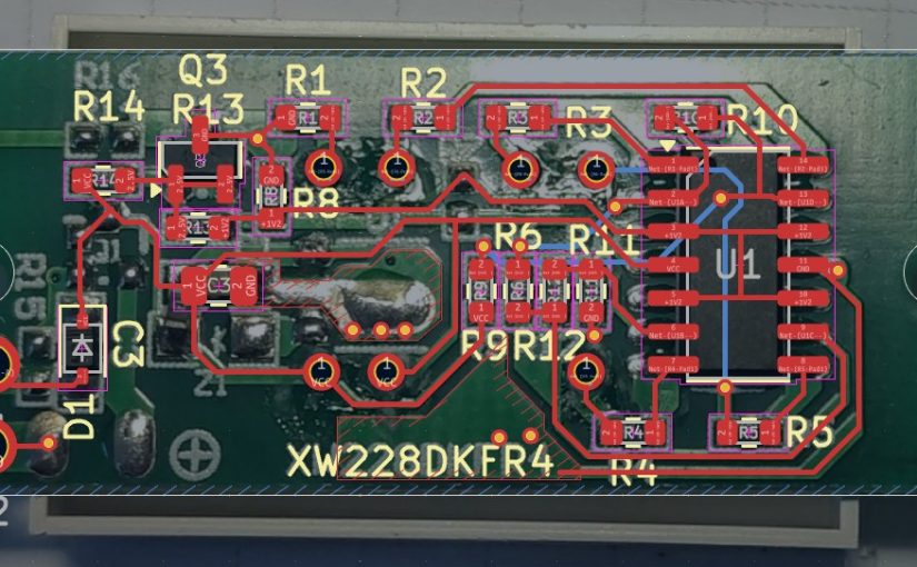
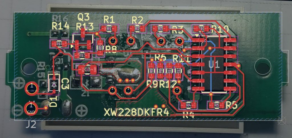
I made a picture of the board, and traced it in KiCad.
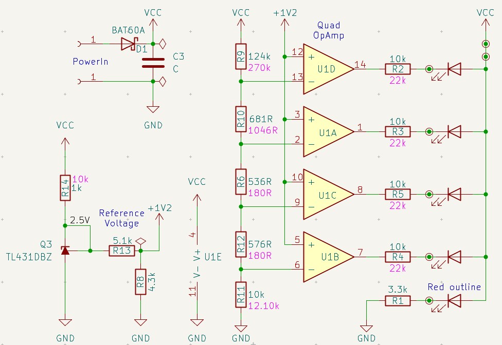
The schematic is quite simple:
- A protection diode on the input
- Reference-Voltage generation using a 431 type
- A four-tap voltage divider
- A quad OpAmp used as comparator
So to make it work with out new voltage range, we just need to adjust the voltage divider. And because the voltage is higher, we also change the LED-Resistors and the TL431 current limiting resistor. The new values are written in pink, the original values are blue in the above schematic.
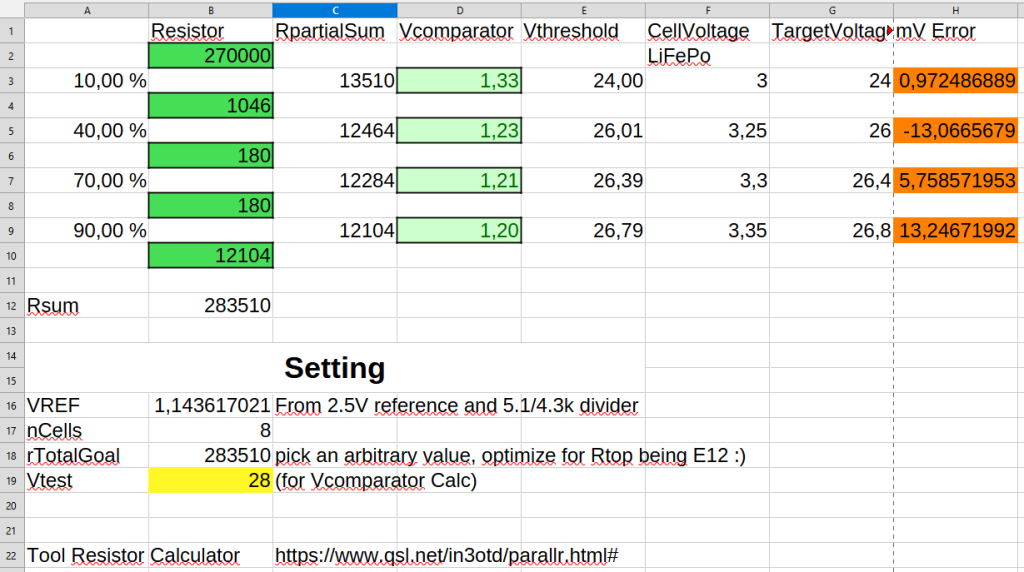
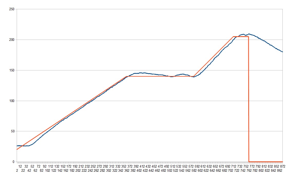
The trick to this calculation is to set the rTotalGoal resistor first, and then start changing the values in column B so that the Vthreshold matches the TargetVoltage as close as possible. The cell B10 is calculated so that the sum of all the resistors is rTotalGoal and changing one resistor does not change the whole calculation.
I used the https://www.qsl.net/in3otd/parallr.html# resistor calculator to get solutions for the weird resistor values. For example 12104 is 22k||27k.