Fix broken pins on QFP Package

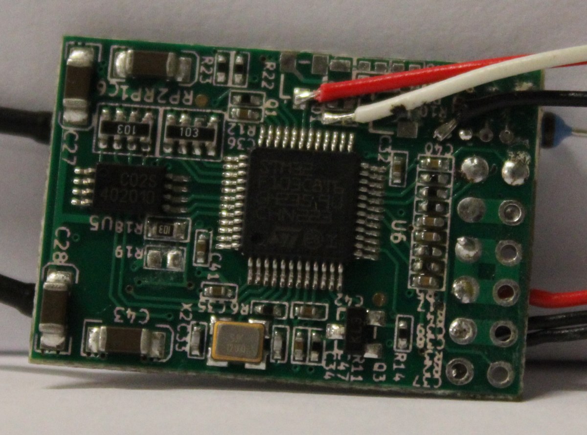
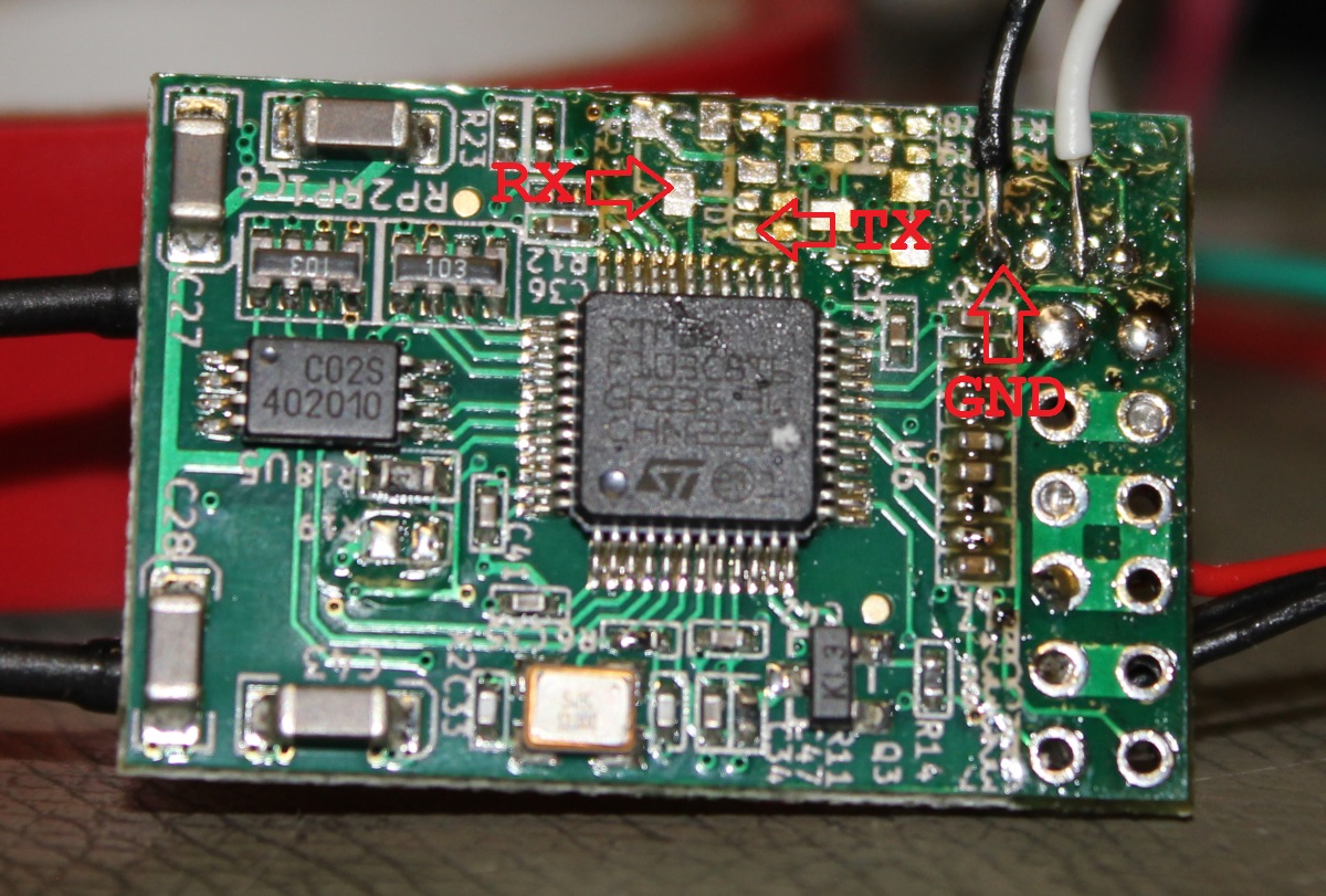
That is how my new HW-0.30-mini Quadcopter Flightcontrol looked prior to the repair:

broken pins

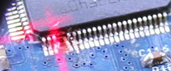
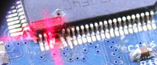
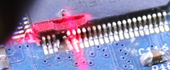
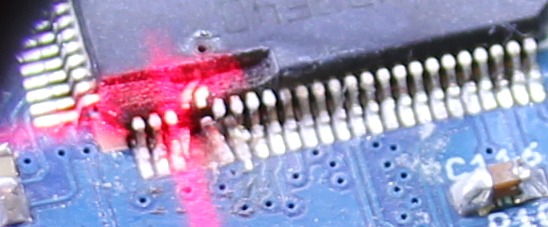
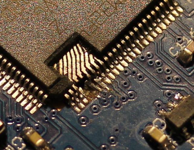
Since a few of the Pads already were delaminated I decided to do a repair instead of soldering in a new CPU. For a repair I would need to get rid of the expoxy mold to directly acces the pins of the leadframe. Initially I was thinking of using a ‘dreml’ tool to remove the exoxy, but watching the Uncaging Microchips talk at 31C3 taught me that using a CO2-Laser will also work.

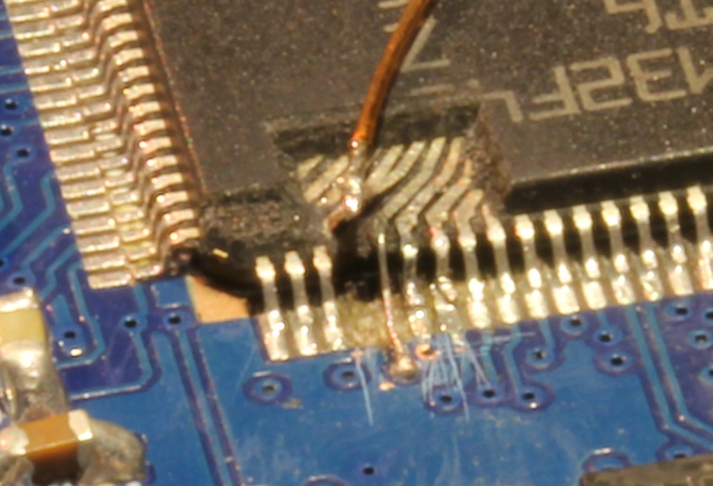
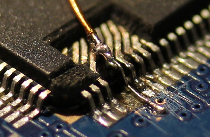
Those pictures were taken during the laser-removal:


After lasering, all left to do was attach new wires. I did use a microscope for that. For scale, the wire running on top of the CPU has a 0.3mm diameter.

I ran some quick tests with the software to make sure the repair worked. Then a blob of hotmelt was applied to secure and protect the repaired pins:

HW-0.30-mini fixed


Backstory: I am also responsible for breaking the pins. I did solder the CPU at 31C3 without proper lighting using borrowed equipment. The temperature on the soldering iron was set to 450°C, I failed to check that. This lead to some major fuckup. Since I wanted to work with the board, the decision was made to simply cut of the broken pins. At the time I didnt need them.

Modding a Futaba FC18-Remote

Today i finished the modification of my remote 🙂

Its an old Futaba FC18v3. I still had that one left from my first experiences with model aircrafts 15 years ago. I hate throwing stuff away, so I bought some new bits to make it usable again.

Now it features:

  • Powered with a 3C-Lipo (not shown in the pictures)
  • Blue Backlight LC-Display
  • FrSky DHT Transmitter module
  • Bluetooth interface for FrSky telemetry

The complete setup draws about 150mA @9V (with all modules powered on). That will make it run more than 10hours with a 1800mAh LiPo.

The Bluetooth and LCD module were both ordered from Ebay, the FrSky stuff from Hobbyking.

The installation of the different parts was pretty straightforward.  I removed the old 40Mhz-PPM-Transmitter and soldered the 3 wires for the new 2.4Ghz module. The old antenna was removed, also i moved the CAMPAC module in order to use that space for the additional LED-and-pushbutton-PCB of the trasmitter module. The Bluetooth module only has 4 pins, GND,+5V,Rx,Tx which i all hooked up to the FrSky. Since the FrSky-Pins are RS232, i modded the module to output TTL-Signals by accessing the UART directly. Unfortunately i didn document that, but you can find several images on google how to do that.

Changing the LCD-Module also was quite easy. Its a standart HD44780 module with a 14Pin connector. Some of the pins are not used because the FC18 runs the display in 4bit-mode. Basically i just removed the old module and soldered the wires 1:1 to the new one. Then i added two wires for the backlight which also runs of 5V.

The last part was setting up data display on my smartphone. Fortunately some other people already took care of that. I just installed FrSky Dashboard. Done 🙂

Reworking a FrSky D4R-II Receiver

Since i want to use telemetry with my soon-to-be-finished uavp-ng quadcopter i decided to use a FrSky two-way-telemetry system. Unfortunately the enigneers at FrSky choose to invert the serial signal which wont work on the hw0.24-mini.

Thats why i took a closer look at the receiver pcb. Fortunately it was quite easy to identify the UART-Pins with TTL levels. I removed the two transistors and some resistors which arent needed anymore.

The pinheader was also removed in this process. I added a bridge on ch3&4 to active CPPM-mode.

As a additional modification  a voltage divider was installed. The AD2-Input of the receiver works up to 3.3Volt. With a 3k3 and a 10k resitor i was able to build a network with a convenient 1:4 scale factor. With 4*3.3Volt > 13V i can monitor the voltage of a 3S LiPo 🙂

Building a quadcopter – Electronics

This is how my Workspace looks after a few hours of debugging 🙂

I did some work on quadcopter-frames in the past, so inspired by the NG-UAVP-Project i decided to build my own quadcopter.

Since those guys offer blank PCBs i ordered some and build a Flight-Controller (hw0.24-mini-r2) and a Quad-Brushless-Controller (ngblc-r2). After some trouble with customs/taxes and missing parts i was finally able to assemble and test both boards. As always not everything works out of the box (soldering errors, missing parts, …).

  • Make sure to populate R68/R69. Those are current-limiting resistors for the backup battery for the Venus-GPS and the RTC. I left them open in the first place sind i didnt populate the battery. However, the Venus-GPS needs power at the Vbat-Pin to work. I spend about 3 hours searching for errors in the serial-communication :/
  • Check the supply voltages of each chip. The coil in the the LC-Filter for the MPU-Accellerometer was broken; however the MPU somehow still worked (eg got some supply current over clamping diodes), but did not answer SPI-requests correctly.
  • Cabeling is also an issue. The picoblade connectors are nice and small, but sometimes dont give good contact. I had some issues with the external-i2c-sensor bus because one pin didnt provide good contact.

There are still some open issues:

  • The LIS3L-Accelerometer wont get recognized on the SPI-Bus
  • On the ngblc there seems to be at least on misplaced part. On of the supply-voltages drops down because of overcurrent. I am still investigating this.


As next steps i will finish the mechanical setup. Mount the motors to the frame and do some wiring.