Modding a Futaba FC18-Remote

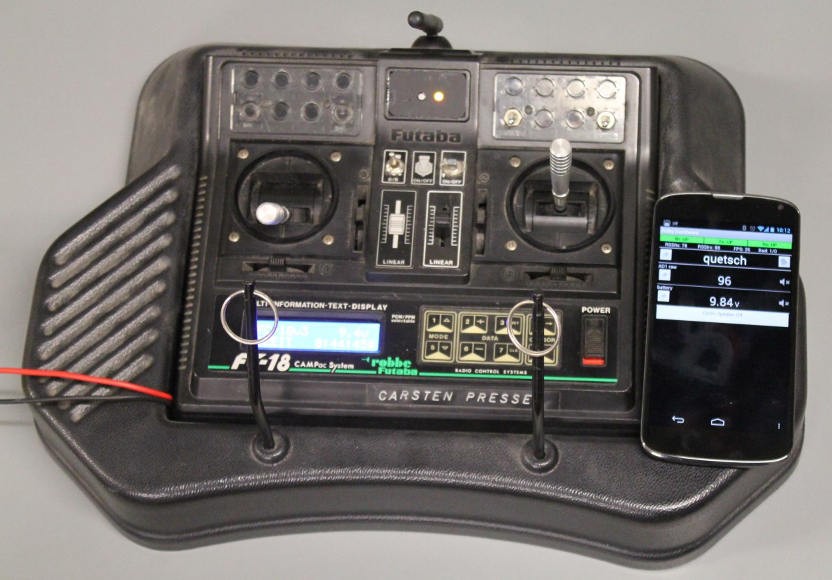
Today i finished the modification of my remote 🙂

Its an old Futaba FC18v3. I still had that one left from my first experiences with model aircrafts 15 years ago. I hate throwing stuff away, so I bought some new bits to make it usable again.

Now it features:

  • Powered with a 3C-Lipo (not shown in the pictures)
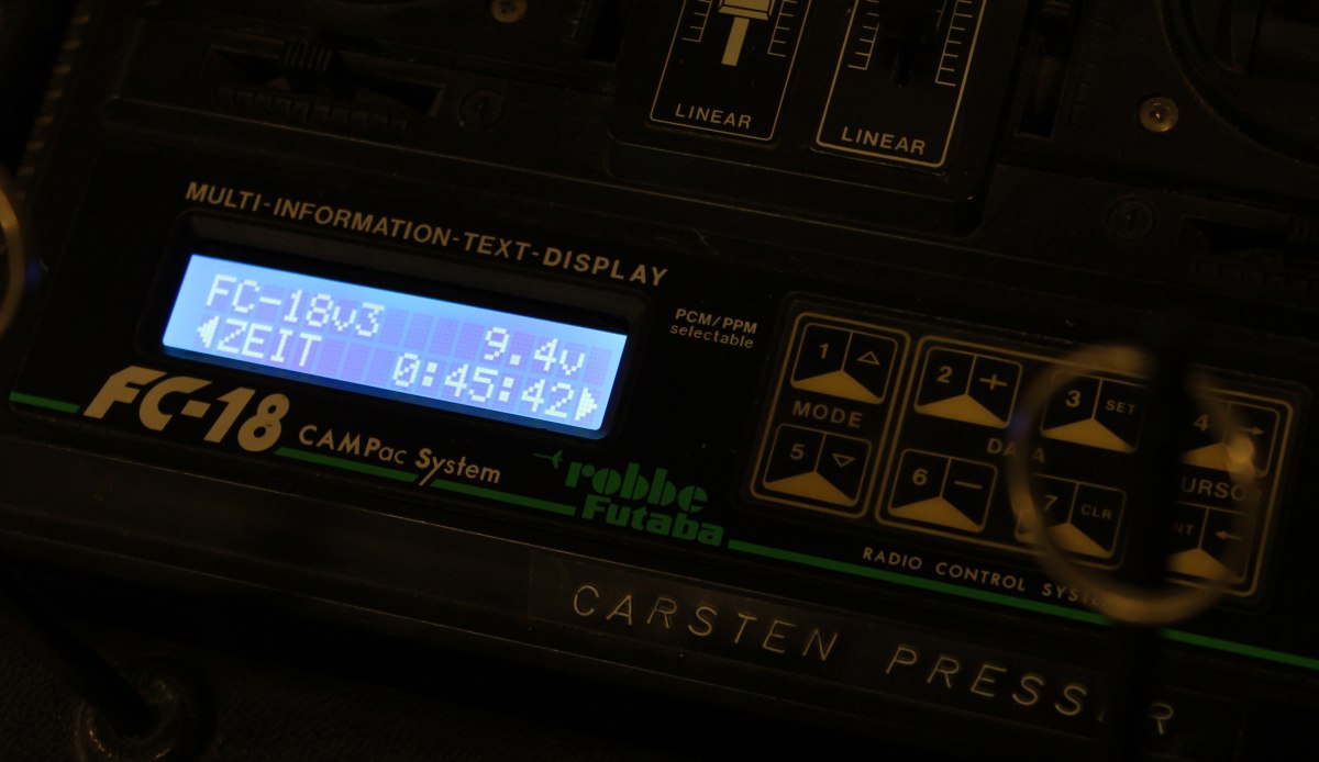
  • Blue Backlight LC-Display
  • FrSky DHT Transmitter module
  • Bluetooth interface for FrSky telemetry

The complete setup draws about 150mA @9V (with all modules powered on). That will make it run more than 10hours with a 1800mAh LiPo.

The Bluetooth and LCD module were both ordered from Ebay, the FrSky stuff from Hobbyking.

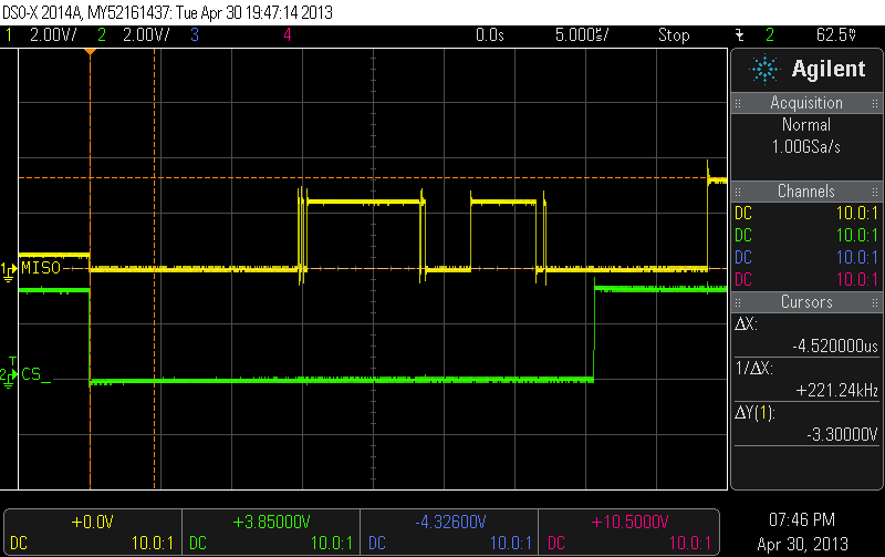
The installation of the different parts was pretty straightforward.  I removed the old 40Mhz-PPM-Transmitter and soldered the 3 wires for the new 2.4Ghz module. The old antenna was removed, also i moved the CAMPAC module in order to use that space for the additional LED-and-pushbutton-PCB of the trasmitter module. The Bluetooth module only has 4 pins, GND,+5V,Rx,Tx which i all hooked up to the FrSky. Since the FrSky-Pins are RS232, i modded the module to output TTL-Signals by accessing the UART directly. Unfortunately i didn document that, but you can find several images on google how to do that.

Changing the LCD-Module also was quite easy. Its a standart HD44780 module with a 14Pin connector. Some of the pins are not used because the FC18 runs the display in 4bit-mode. Basically i just removed the old module and soldered the wires 1:1 to the new one. Then i added two wires for the backlight which also runs of 5V.

The last part was setting up data display on my smartphone. Fortunately some other people already took care of that. I just installed FrSky Dashboard. Done 🙂

Building a quadcopter – Electronics

This is how my Workspace looks after a few hours of debugging 🙂

I did some work on quadcopter-frames in the past, so inspired by the NG-UAVP-Project i decided to build my own quadcopter.

Since those guys offer blank PCBs i ordered some and build a Flight-Controller (hw0.24-mini-r2) and a Quad-Brushless-Controller (ngblc-r2). After some trouble with customs/taxes and missing parts i was finally able to assemble and test both boards. As always not everything works out of the box (soldering errors, missing parts, …).

  • Make sure to populate R68/R69. Those are current-limiting resistors for the backup battery for the Venus-GPS and the RTC. I left them open in the first place sind i didnt populate the battery. However, the Venus-GPS needs power at the Vbat-Pin to work. I spend about 3 hours searching for errors in the serial-communication :/
  • Check the supply voltages of each chip. The coil in the the LC-Filter for the MPU-Accellerometer was broken; however the MPU somehow still worked (eg got some supply current over clamping diodes), but did not answer SPI-requests correctly.
  • Cabeling is also an issue. The picoblade connectors are nice and small, but sometimes dont give good contact. I had some issues with the external-i2c-sensor bus because one pin didnt provide good contact.

There are still some open issues:

  • The LIS3L-Accelerometer wont get recognized on the SPI-Bus
  • On the ngblc there seems to be at least on misplaced part. On of the supply-voltages drops down because of overcurrent. I am still investigating this.


As next steps i will finish the mechanical setup. Mount the motors to the frame and do some wiring.