Controlling WS2812 LED-Pixels from an Raspberry-Pi can be done. Other people have done this before: https://github.com/jazzycamel/ws28128-rpi/
My approach is different, but not that new either. I already implemented similar code for the Lightpainting-Stick-Clone.
To get the required timing with the SPI we can output some patterns to make it look like the WS2812-Protocol.
However, there are some issues as metioned in the inline-comments. At first it seems like the code does not work when sending dmx-data with ola_dmxconsole. Once there are more changes in a short period of time, the pixels start to react. My guess here that this is related to the scheduler of the kernel. When as the kernel switches tasks the SPI output-stream gets interrupted, thus making the timing invalid. I will investigate this further.
void SPIOutput::IndividualWS2812Control(const DmxBuffer &buffer) {
/*
* This is an hack!
*
* Basically the RaspberryPI cant drive WS2812 Pixels because they have
* some strict timing requirements.
* Using the SPI-Module we can emulate those pulses.
* This will only work if the SPI-Module outputs all data in one consecutive
* stream without any pauses. More recent versions of the Raspberry Kernel
* seem to implement DMA for SPI which makes this possible.
*
* WS2811-Chips have similar timings but not exactly the same as WS2812.
* Some sources say the most important part is the total period-time
* of one bit. There are lots of descriptions of WS2812-timing requirements
* out there, one of them is: (with +-150ns tolerance)
* 0-Bit 0.25us high, 1us low
* 1-Bit 0.6us high, 0.65us low
*
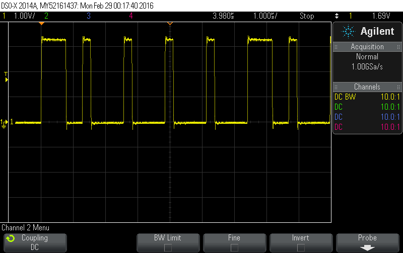
* Running the SPI at 4Mhz gives us a pulse-width of 250ns
* Using a 5-bit pattern we can emulate those timings
* 0-Bit: 10000 (0.25us high, 1us low)
* 1-Bit: 11110 (1us high, 0.25us low)
* Those values are not an exact match, but they seem to work for both
* WS2812 and WS2811 in high-speed-mode.
*
* We need to send 8 of those 5-packs for each byte. Those 40 bits are
* precalculated and stored in a lookup table.
*
* To issue an reset, the data-line needs to be low for 50us, thats
* 200 bits, or 25 bytes. For safety, we will send 27 bytes.
*
* Connect the Data-In-Pin of the LEDs to the MOSI Pin of the SPI-Module,
* ignore the clock Pin.
*
*/
const uint8_t reset_bytes = 27;
const unsigned int first_slot = m_start_address - 1; // 0 offset
// We always check out the entire string length, even if we only have data
// for part of it
const unsigned int output_len = reset_bytes + m_pixel_count *
WS2812_SLOTS_PER_PIXEL * WS2812_SPI_LUT_LEN;
uint8_t *output = m_backend->Checkout(m_output_number, output_len, 0);
if (!output)
return;
// set the reset-bytes to zero
memset(output, 0, reset_bytes);
// loop over all pixels
unsigned int output_pos = reset_bytes;
for (uint16_t px = 0; px < m_pixel_count * WS2812_SLOTS_PER_PIXEL; px++) {
uint8_t c = buffer.Get(px + first_slot);
// now output 5 bytes from the LUT
for (unsigned int lut = 0; lut < WS2812_SPI_LUT_LEN; lut++) { output[output_pos++] = WS2812_SPI_LUT[c * 5 + lut]; } } m_backend->Commit(m_output_number);
}
I pushed that code here: https://github.com/cpresser/ola/tree/ws2812-spi
This is the config I used:
base_uid = 7a70:00000100
device_prefix = spidev
enabled = true
spidev0.0-0-device-label = SPI Device - spidev0.0
spidev0.0-0-dmx-address = 1
spidev0.0-0-personality = 9
spidev0.0-0-pixel-count = 10
spidev0.0-backend = software
spidev0.0-ports = 1
spidev0.0-spi-ce-high = false
spidev0.0-spi-speed = 8000000
spidev0.0-sync-port = 0
Demo time: