I bought my el-cheapo chinese lasercutter without a pilot laser. They did offer a visible laser for alingment, but that was just a simple laser-pointer mounted next to the main-laser-nozzle. It was kind of expensive (despite the fact that it was a really simple non-coaxial-design) so i decided to build my own.
From ebay i got two laser-modules in a cylindrical housing for about 21€ including shipping which already produce a line (they have a prism build in).
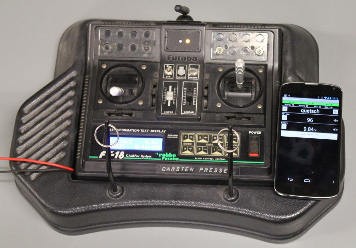
IÂ order to mount them i designed and build a bracket out of 12mm acrylic. Basically its a ring with a slot, i can slide it up the nozzle and fix its positin by tightening a screw. You can see how it looks mounted to the machine in the first picture.
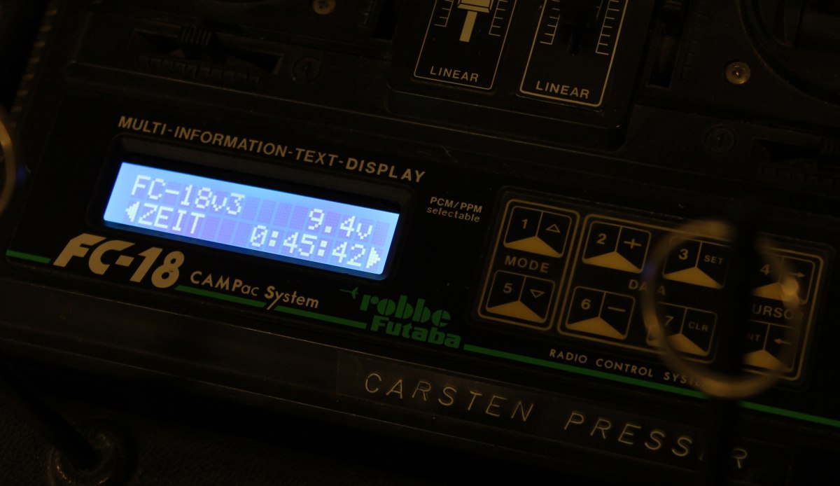
Unfortunately i wasnt able to mount it further down on the nozzle. Now the laser angle is to steep and part of the laser is blocked by the nozzle itself (you can see the laser on the nozzle in the second picture). I managed to adjust it in a way that at least the pilot lasers cross in one point. Alignment in parallel to the working area required a little patience, but somehow i managed:


As a last job i wired everything up and slid the cables through the drag-chain. Since i was already soldering and installing additional wires, i also added two LED-Stripes to the portal to have better illumination while working.