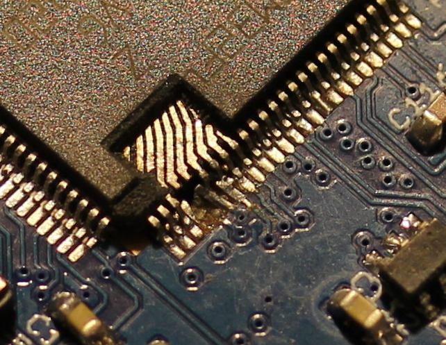
That is how my new HW-0.30-mini Quadcopter Flightcontrol looked prior to the repair:

Since a few of the Pads already were delaminated I decided to do a repair instead of soldering in a new CPU. For a repair I would need to get rid of the expoxy mold to directly acces the pins of the leadframe. Initially I was thinking of using a ‘dreml’ tool to remove the exoxy, but watching the Uncaging Microchips talk at 31C3 taught me that using a CO2-Laser will also work.
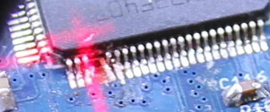
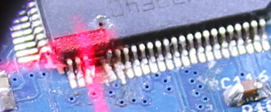
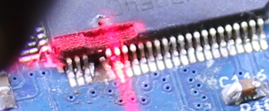
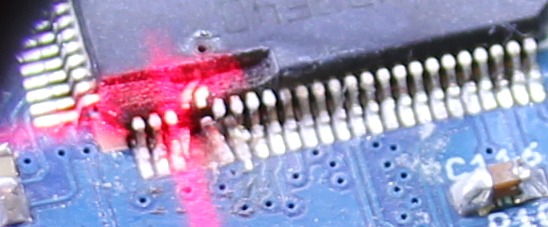
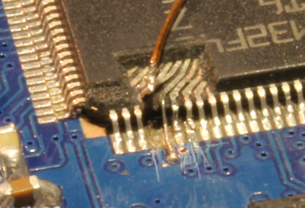
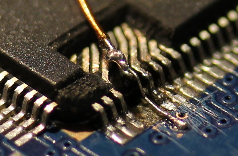
Those pictures were taken during the laser-removal:

After lasering, all left to do was attach new wires. I did use a microscope for that. For scale, the wire running on top of the CPU has a 0.3mm diameter.
I ran some quick tests with the software to make sure the repair worked. Then a blob of hotmelt was applied to secure and protect the repaired pins:

Backstory: I am also responsible for breaking the pins. I did solder the CPU at 31C3 without proper lighting using borrowed equipment. The temperature on the soldering iron was set to 450°C, I failed to check that. This lead to some major fuckup. Since I wanted to work with the board, the decision was made to simply cut of the broken pins. At the time I didnt need them.
This is awesome to a new level. Even after seeing the decapping of a blobbed chip in HaD, It never ocurred to me that you could also do this.
My hat’s off to you!
Man, that’s awesome repair work.
I never thought of using a CO2 laser to remove the epoxy-mold/package to expose the leadframe.
The only successful similar repair I made was using a micro-drill to drill down through the epoxy into the lead inside. Then ran a fluxed wire down into the hole. It drew the solder in to make the connection.
Although my repair was a while back, before SMT components became common.
A laser powerful enough to burn plastic, aimed at an area containing shiny metal surfaces… how were you watching / guiding the process?
Did you watch via video camera, did you wear safety goggles – or did you just “eyeball” it and risk permanent damage from reflections?
Alignment: I have visible alignment-lasers mounted to the nozzle. They arent that acurate (+-0.5mm), so I had an extra program to mark a spot on the IC. Then I moved the Chip accordingly.
Protection: I closed the Lid of the laser-cutter, inspection & pictures were done inbetween passes.
By any chance, did you film the process?
What brand and model of CO2 laser did you use?
Hello,
Nice result ! What’s the power of the laser ? Can you, please, tell us more about the laser settings (speed, power, number of pass, process duration, etc…)
I used a noname chinese laser-cutter with 80W tube and 600x400mm working area.
To remove the epoxy I used the engraving-function with 25% power and 200mm/sec speed. Each pass removed ~0.2mm of material.
The whole removal-process including alignment took about 40minutes.
@Alejandro: sorry, no video. Just the pictures in the blogpost above.
how were you watching / guiding the process?
@Jefry
I did small passes, roughly 0.1 – 0.2mm on each engraving-pass. Inbetween, I did open the enclosure and did take a look ath the chip. Thats also how the pictures were made.
As soon as the lead-frame was visible, I stopped lasering.
wieso der teure laser, eine Fräse hätte das auch geschafft ?