Gendered Connectors in Electronics

Using the male/female terminology for connectors seems to be the industry standard. In the past I have never questioned this. Its just how things are and how I learned to work with them.
In one of my recent KiCad-Workshops I talked to people that would like to get rid of those words. There are a few issues with using the sex-analogy:

  • Its not always clear what exactly is male. Quite a few connectors that are “inserted” are considered female. There are also female connectors that have protruding pins[1].
  • The language is non inclusive
  • Not all vendors use the same terminology

There has been some movement in the industry to address this problem. One example is the PAMA Recommendations for Neutral Nomenclature in Pro Audio from the Professional Audio Manufacturers Alliance (PAMA).

The proposed solution is to replace male/female with plug/socket, or pin/receptacle depending on the actual connector.
This is quite clever, since it solve the ambiguity of male what means: ‘will be inserted’ vs. ‘does have pins’.

There is no good reason why we, as an open-source community, should not improve our naming. On the contrary, we are not bound by weird corporate rules, but have the ability and freedom to be a leader of change. Both in the technical and inclusion aspect.

So lets do some research next, to see if and how we can untangle this Goardian knot.

D-Subminiature connectors

There are way to many different connectors out there to research them all. So I decided to start with the D-Sub type since they are well known and lots of manufacturers make them. Also there are standard documents describing them.

Vendors

When looking at how vendors name their connectors, there is not a single truth[2].


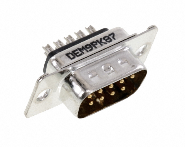
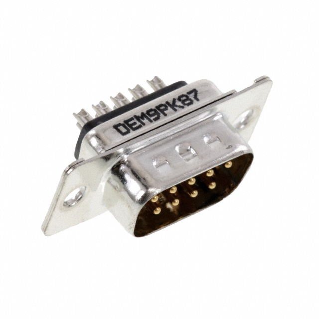
A “male”[3] D-Subminiature DE-9[4] connector. It has a shroud (the metal shell surrounding the pins). One can argue that the counterpart gets inserted into this connector. So this should be female?
We will learn later that at least for this type of connector, male == pins. Which is a good argument to just call it pins since its less ambiguous.

VendorPart numberNamingLink
Amphenol ICCD/8656/ DP SERIESPin/Sockethttps://www.amphenol-cs.com/media/wysiwyg/files/documentation/datasheet/inputoutput/io_dsub_d8656.pdf
Tyco Electronic1-5747150-3Receptaclehttps://www.te.com/usa-en/product-1-5747150-3.html
Würth210111003Malehttps://www.we-online.com/katalog/datasheet/210111003.pdf
Canon ITTDE-9P-K87Pinhttps://media.digikey.com/pdf/Data Sheets/ITT PDFs/DE-9P-K87.pdf
JAEDE-9SF-NPin/Sockethttps://www.jae.com/direct/topics/topics_file_download/?topics_id=66362&ext_no=06&index=0&_lang=en
Assmann WSWA-DF 09 LL/ZMale/Femalehttp://www.assmann-wsw.com/uploads/datasheets/ASS_4884_CO.pdf
NorComp171-009-103L001Male/Femalehttps://content.norcomp.net/rohspdfs/Connectors/17Y/171/171-YYY-10YLYY1.pdf
3M8200 & 8300 SeriesPlug/Receptacle/Sockethttps://www.3m.com/3M/en_US/p/c/electronics-components/interconnect-products/input-output-connectors/d-shaped/
Molex1727040160Malehttps://www.molex.com/webdocs/datasheets/pdf/en-us/1727040160_DSUB_PRODUCTS.pdf

There are at least 20 different vendors for DE-9 connectors on Digikey, I did not check all of them. That is not needed, it is quite obvious that vendors don’t agree on naming.

Other PCB tools

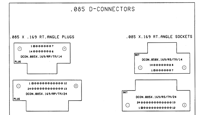
Orcad® Layout

Uses Plug & Socket

Source: http://ohm.bu.edu/~pbohn/__Engineering_Reference/pcb_layout/Footprints.pdf

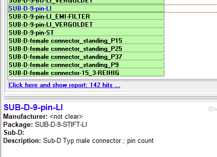
Target 3001!

Uses STIFT (=pin) and male at the same time.

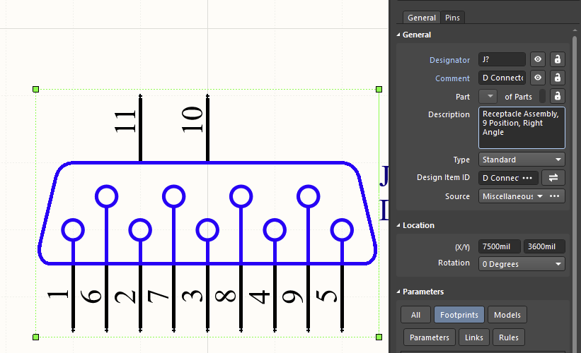
Altium Designer

Uses Receptacle

Standard documents

Okay, next up we take a closer look at the standard documents. There are quite a few different standards to consider.

German DIN 41652 (D-Sub connectors)

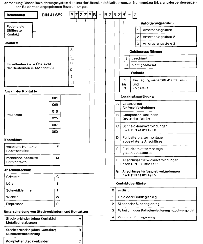
The German DIN uses

  • F = female contacts – spring contacts
  • M = male contacts – pins

The interesting part here is that the proper letter would be W (weiblich) instead of F to indicate the gender. One could argue that the F stands for Federkontakte. Most likely, this is just a translation issue (as in the letters are not translated at all). I guess the letters (m/f) are supposed to indicate gender.
What is clear here, the male/female wording aims at the pins, not the connector shell.

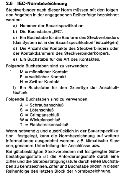
International IEC 60807-2

Unfortunately I only have the German translation of this. Its pretty similar to the the same as DIN 41652:

MIL-C-24308C

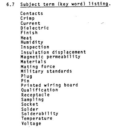
I could not find the words male or female in there at all. The document always refers to “plugs and receptacles”. The key word listing has pin/socket and plug/receptacle.

Data for other connectors

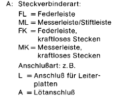
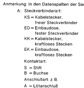
DIN 4000-54 “Sachmerkmal-Leisten”

This norm has rules that specify how different connectors should be described.
The tables that describe the contact don’t mention male/female. Instead Messer/Feder (translated to Socket/Pin) is used.

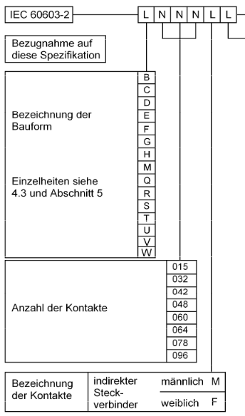
DIN EN 60603-2 (Replaces DIN41612)

Those are connectors used in rack systems. See https://en.wikipedia.org/wiki/DIN_41612 for some pictures.
The connectors of this series are named male/female in the spec.

Interestingly enough, TE calls them Plug/Receptacle.

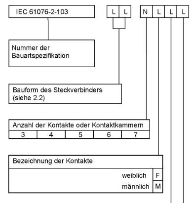
XLR (EN 61076-2-103:2004)

The connectors of this series are named male/female in the spec.
As far as I can tell, vendors (Neutrik, Switchcraft) also choose this naming scheme.

So what does ‘inclusive language’ actually mean?

That is hard, perhaps impossible for me to answer. I have always been included in a tech environment. As a member of the dominant culture I don’t experience microagressions when reading those words.
Other people however are affected by this language. Those asked me to do something about it. I want KiCad to be a safe space for anybody. That’s my main motivation to change things.
Given how small the cost of a change is, I am much in favor of getting rid of non-inclusive words.

Conclusion

We learned that there is no single truth, thus we need to weight our options.
Regarding the KiCad-Library I made the following decisions:

  • D-Subminiature rename to Pin/Socket.
    • Solves the confusion about what is considered male
    • About half of the vendors use that naming
  • XLR and DIN EN 60603-2
    • Stick with male/female
    • Its consistent with vendor naming and standards
    • Its still ambiguous 🙁
  • Connector_Generic
    • They are generic, with no footprint and thus not vendor associated
    • The names are made up, so we can just change them as we like
    • Pin/Socket seems like a good fit
  • RJ45 Jacks (I did not explicitly research them)
    • everybody already calls them jacks
    • Just rename them to jack or socket
  • USB Connectors
    • They don’t have protruding pins
    • The spec does specify what a jack and plug is

I get that people will be unhappy with this change. Or on the contrary, argue that even the XLR-Connectors need to be renamed now. Saying that I don’t care about other peoples opinion would be a lie. I obvious do, otherwise I would not have spend this much time and effort on trying to making KiCad more inclusive.


  1. Applies to the “Reverse” SMA or BNC connectors
  2. as always with electronic components. There is at least one vendor that has a totally different system.
  3. also known as “Plug” or “Pin”
  4. a common misconception is to call this connector DB-9 which is technically wrong.

Fix broken pins on QFP Package

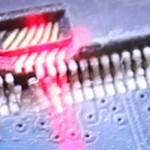
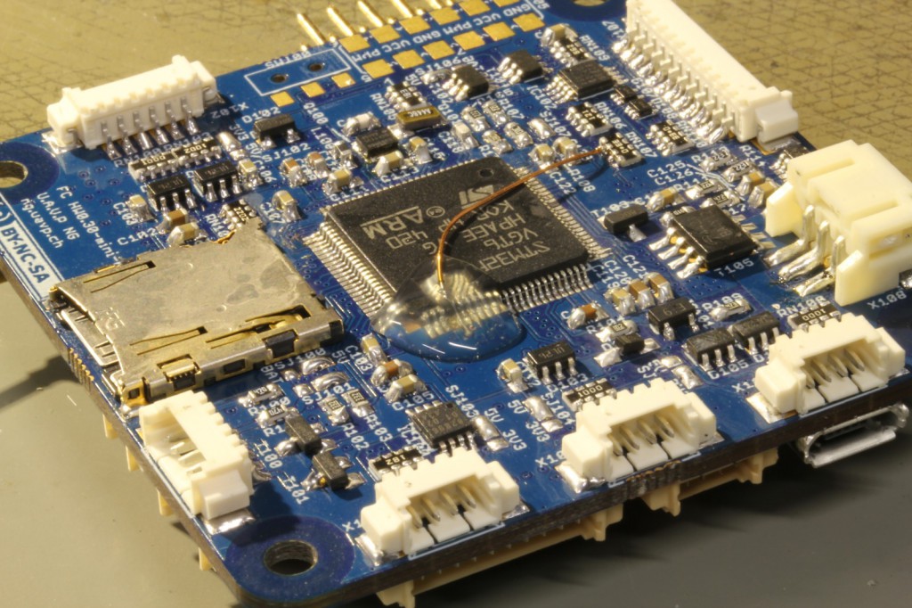
That is how my new HW-0.30-mini Quadcopter Flightcontrol looked prior to the repair:

broken pins

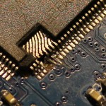
Since a few of the Pads already were delaminated I decided to do a repair instead of soldering in a new CPU. For a repair I would need to get rid of the expoxy mold to directly acces the pins of the leadframe. Initially I was thinking of using a ‘dreml’ tool to remove the exoxy, but watching the Uncaging Microchips talk at 31C3 taught me that using a CO2-Laser will also work.

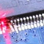
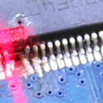
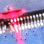
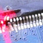
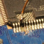
Those pictures were taken during the laser-removal:


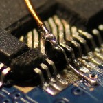
After lasering, all left to do was attach new wires. I did use a microscope for that. For scale, the wire running on top of the CPU has a 0.3mm diameter.

I ran some quick tests with the software to make sure the repair worked. Then a blob of hotmelt was applied to secure and protect the repaired pins:

HW-0.30-mini fixed


Backstory: I am also responsible for breaking the pins. I did solder the CPU at 31C3 without proper lighting using borrowed equipment. The temperature on the soldering iron was set to 450°C, I failed to check that. This lead to some major fuckup. Since I wanted to work with the board, the decision was made to simply cut of the broken pins. At the time I didnt need them.

Reworking a FrSky D4R-II Receiver

Since i want to use telemetry with my soon-to-be-finished uavp-ng quadcopter i decided to use a FrSky two-way-telemetry system. Unfortunately the enigneers at FrSky choose to invert the serial signal which wont work on the hw0.24-mini.

Thats why i took a closer look at the receiver pcb. Fortunately it was quite easy to identify the UART-Pins with TTL levels. I removed the two transistors and some resistors which arent needed anymore.

The pinheader was also removed in this process. I added a bridge on ch3&4 to active CPPM-mode.

As a additional modification  a voltage divider was installed. The AD2-Input of the receiver works up to 3.3Volt. With a 3k3 and a 10k resitor i was able to build a network with a convenient 1:4 scale factor. With 4*3.3Volt > 13V i can monitor the voltage of a 3S LiPo 🙂

Building a quadcopter – Electronics

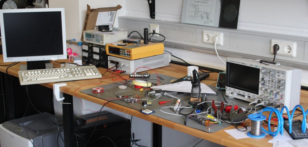
This is how my Workspace looks after a few hours of debugging 🙂

I did some work on quadcopter-frames in the past, so inspired by the NG-UAVP-Project i decided to build my own quadcopter.

Since those guys offer blank PCBs i ordered some and build a Flight-Controller (hw0.24-mini-r2) and a Quad-Brushless-Controller (ngblc-r2). After some trouble with customs/taxes and missing parts i was finally able to assemble and test both boards. As always not everything works out of the box (soldering errors, missing parts, …).

  • Make sure to populate R68/R69. Those are current-limiting resistors for the backup battery for the Venus-GPS and the RTC. I left them open in the first place sind i didnt populate the battery. However, the Venus-GPS needs power at the Vbat-Pin to work. I spend about 3 hours searching for errors in the serial-communication :/
  • Check the supply voltages of each chip. The coil in the the LC-Filter for the MPU-Accellerometer was broken; however the MPU somehow still worked (eg got some supply current over clamping diodes), but did not answer SPI-requests correctly.
  • Cabeling is also an issue. The picoblade connectors are nice and small, but sometimes dont give good contact. I had some issues with the external-i2c-sensor bus because one pin didnt provide good contact.

There are still some open issues:

  • The LIS3L-Accelerometer wont get recognized on the SPI-Bus
  • On the ngblc there seems to be at least on misplaced part. On of the supply-voltages drops down because of overcurrent. I am still investigating this.


As next steps i will finish the mechanical setup. Mount the motors to the frame and do some wiring.