Reworking a FrSky D4R-II Receiver

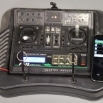
Since i want to use telemetry with my soon-to-be-finished uavp-ng quadcopter i decided to use a FrSky two-way-telemetry system. Unfortunately the enigneers at FrSky choose to invert the serial signal which wont work on the hw0.24-mini.

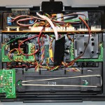
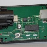
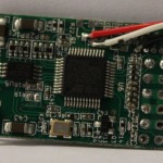
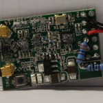
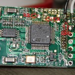
Thats why i took a closer look at the receiver pcb. Fortunately it was quite easy to identify the UART-Pins with TTL levels. I removed the two transistors and some resistors which arent needed anymore.

The pinheader was also removed in this process. I added a bridge on ch3&4 to active CPPM-mode.

As a additional modification  a voltage divider was installed. The AD2-Input of the receiver works up to 3.3Volt. With a 3k3 and a 10k resitor i was able to build a network with a convenient 1:4 scale factor. With 4*3.3Volt > 13V i can monitor the voltage of a 3S LiPo 🙂

Building a quadcopter – Electronics

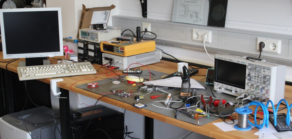
This is how my Workspace looks after a few hours of debugging 🙂

I did some work on quadcopter-frames in the past, so inspired by the NG-UAVP-Project i decided to build my own quadcopter.

Since those guys offer blank PCBs i ordered some and build a Flight-Controller (hw0.24-mini-r2) and a Quad-Brushless-Controller (ngblc-r2). After some trouble with customs/taxes and missing parts i was finally able to assemble and test both boards. As always not everything works out of the box (soldering errors, missing parts, …).

  • Make sure to populate R68/R69. Those are current-limiting resistors for the backup battery for the Venus-GPS and the RTC. I left them open in the first place sind i didnt populate the battery. However, the Venus-GPS needs power at the Vbat-Pin to work. I spend about 3 hours searching for errors in the serial-communication :/
  • Check the supply voltages of each chip. The coil in the the LC-Filter for the MPU-Accellerometer was broken; however the MPU somehow still worked (eg got some supply current over clamping diodes), but did not answer SPI-requests correctly.
  • Cabeling is also an issue. The picoblade connectors are nice and small, but sometimes dont give good contact. I had some issues with the external-i2c-sensor bus because one pin didnt provide good contact.

There are still some open issues:

  • The LIS3L-Accelerometer wont get recognized on the SPI-Bus
  • On the ngblc there seems to be at least on misplaced part. On of the supply-voltages drops down because of overcurrent. I am still investigating this.


As next steps i will finish the mechanical setup. Mount the motors to the frame and do some wiring.

Lasercut Puzzle

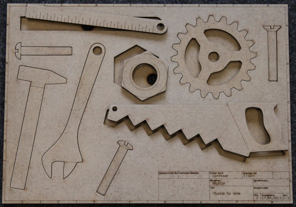
Puzzle made out of 5mm HDFI made this for my niece (currently 16months).

Its made of 5mm HDF wood.  I did a google-image-search to find suitable pictures and traced them in Vcarve.

The text and the DIN-Label-Box in the lower right were exported from eagle. I was to lazy to draw them myself.

In the first version i just cut along the vectors which resulted in a really tight fit. The gear was almost impossible to remove and put in again. For the second version i duplicated the lines with an offset of 0.3mm which did result in a larger gap. Now all the parts fall out by themselfes if you turn the puzzle around.

The two sheets were glued together with basic wood-glue. The lower sheet also features ‘eject-holes’ (you can see them under the ruler and nut). That way you can push out the pieces from behind.