I have done a few PCBs using the reflow process. To apply the solder-paste using a stencil one requires some sort of fixture to hold the PCB.
So far I helped myself with other PCB Material which I glued on the table to get to the same height. This is okay when only one PCB needs to be made. However, when doing multiple PCBs on after another, the position needs to be constant for every board.
So I designed a simple spring loaded fixture to hold the PCB in place. Its made out of 1.5mm acrylic.
Turns out the drives of my Scara Robot are not velocity-mode drives but torque-mode drives instead. Setting the drive input to a constant voltage results in constant accelleration. I learned this the hard way by crashing the robot :-/
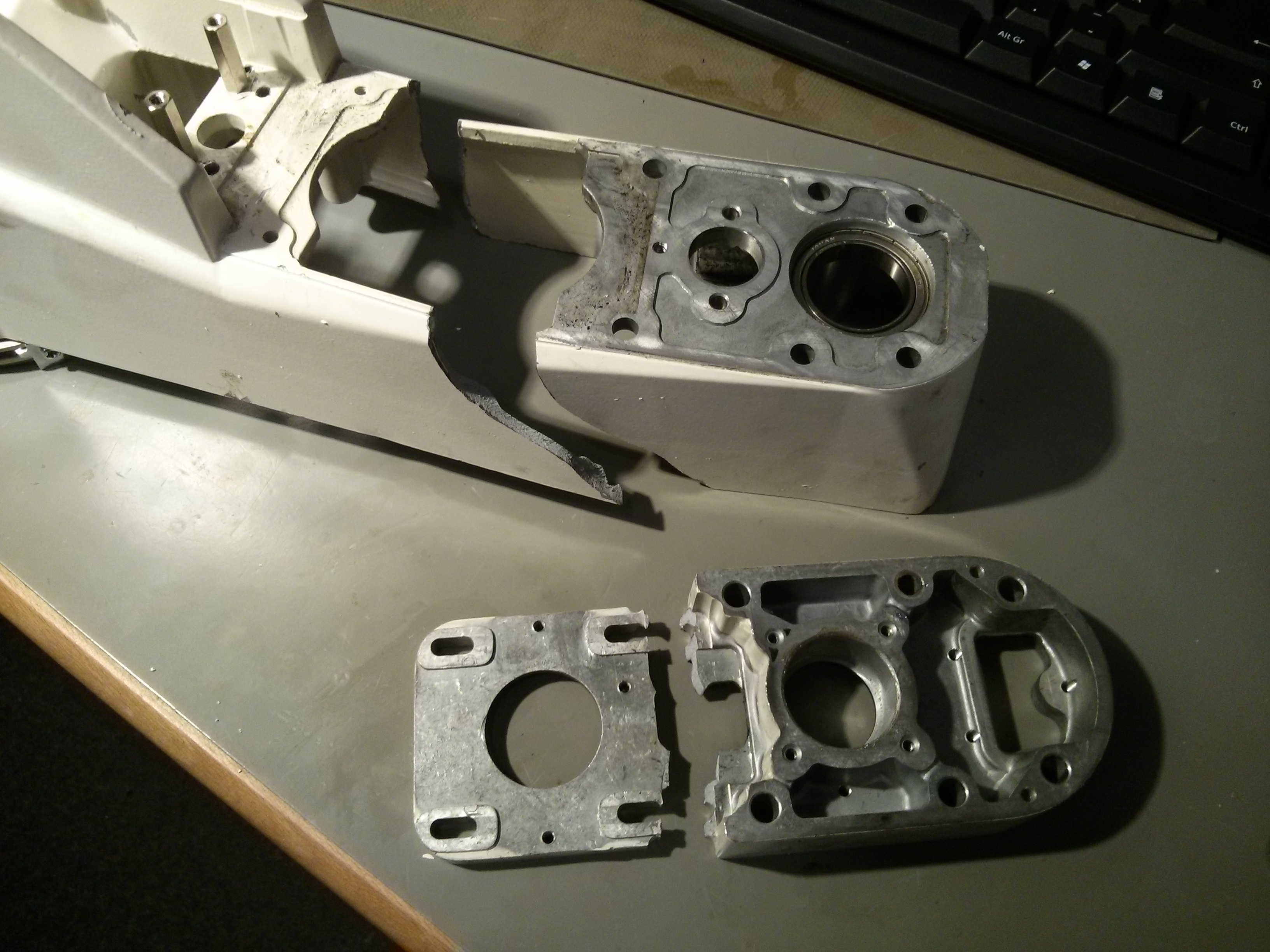
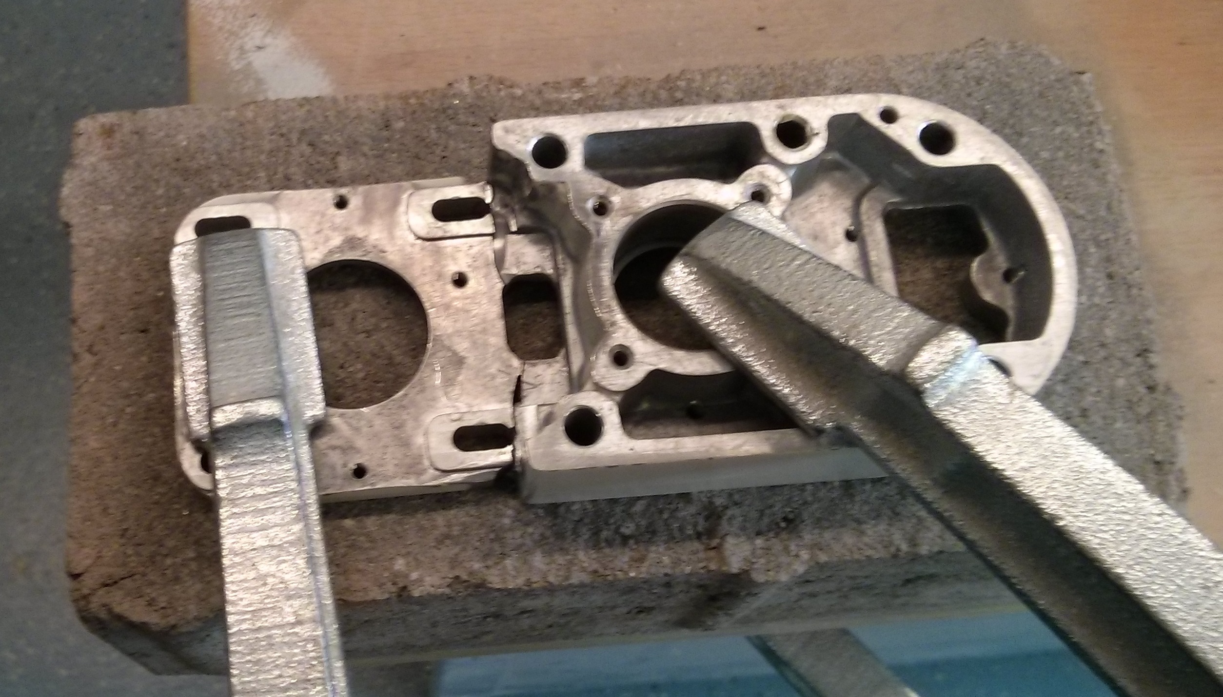
Even though I had it fixed on an Europalette it managed to fall on its side. Second lesson learned: even ‘small’ a 200W drive can turn the whole thing in a fraction of a second. Hitting the floor broke some pieces. But see for yourself:
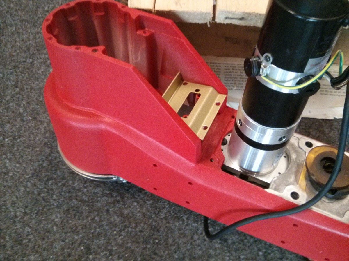
B-Arm and Z-Motor-Plate destruction
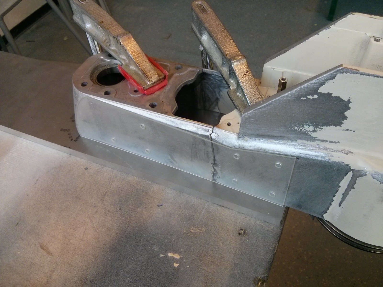
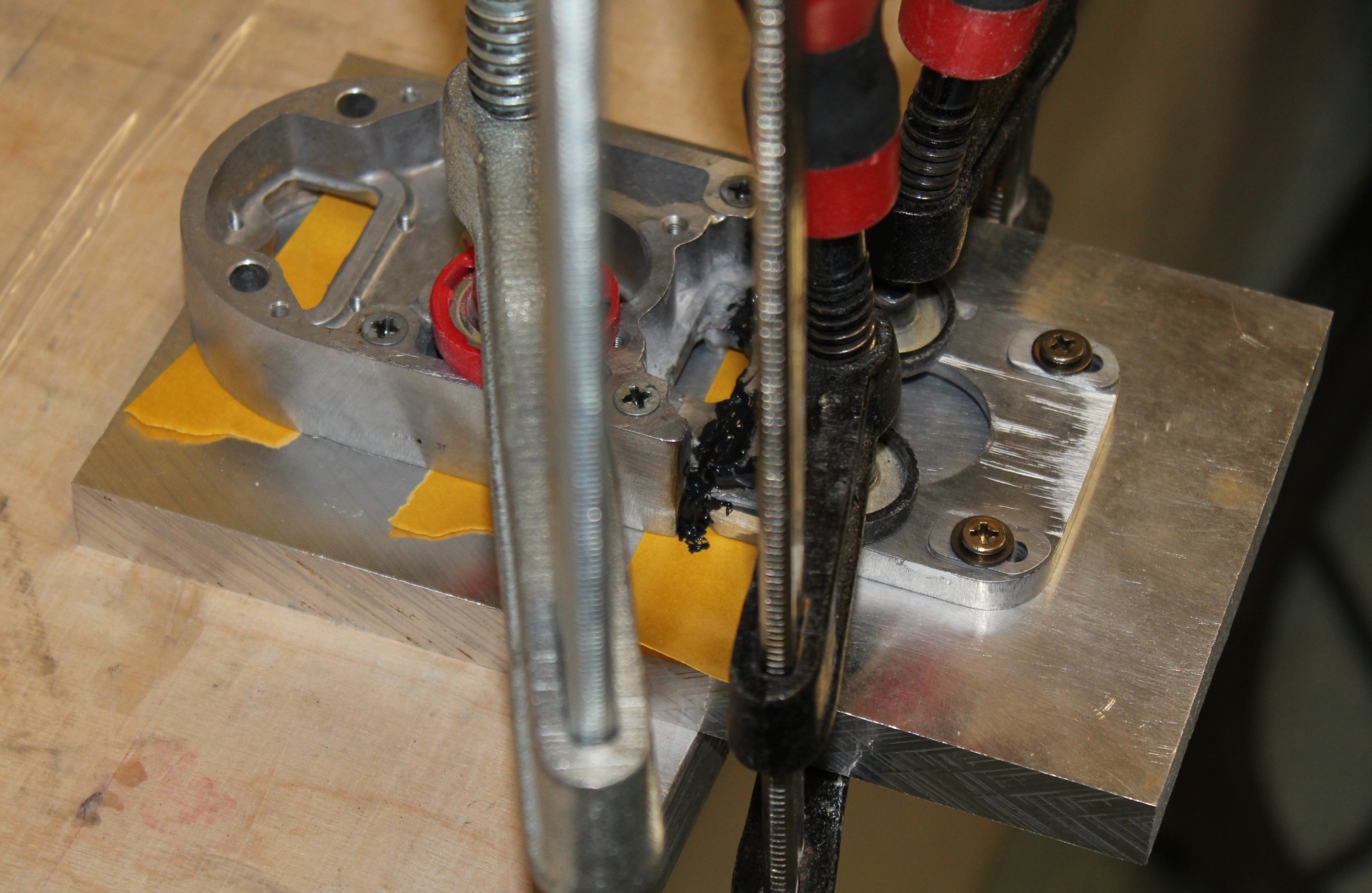
Those parts are both made out of cast aluminium. I do lack the equipment and skill to weld, so I asked a Friend of mine to do it. However, even with his long time experience he wasn’t able to fix the parts together. At first I got desperate and tried hard-soldering the Z-Motor-Mount. But even using two torches I wasnt able to get the part hot enough to accept the solder.
Z-Motor-Plate fixed with clamps ready to solder
As a last resort I deceided to glue the parts. Fortunately my sister works as a postdoc and is an expert for aluminium epoxy bonds. She did some rought calculations for me and helped select the correct adhesive: 3M Scotch-Weld DP490.
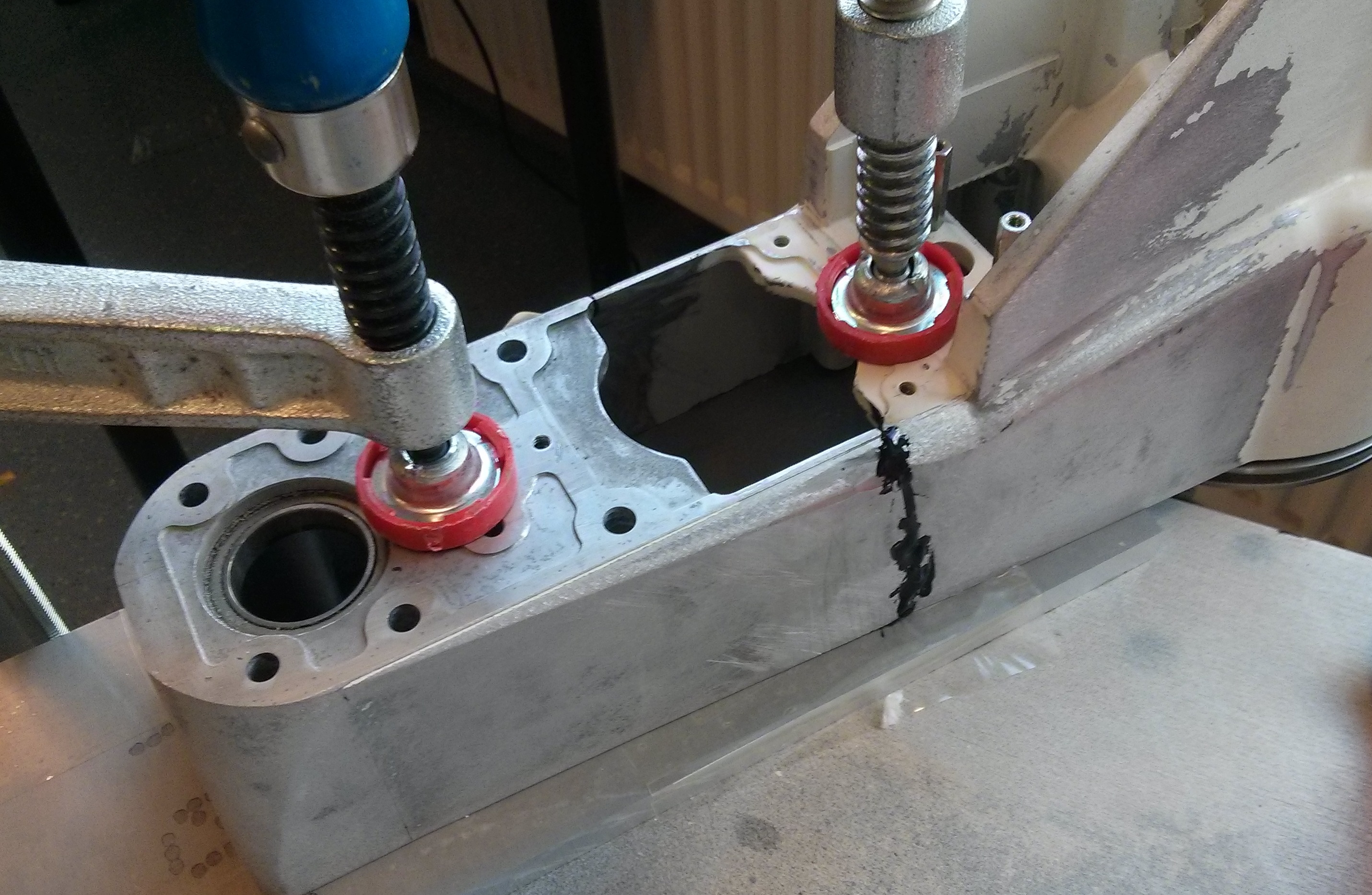
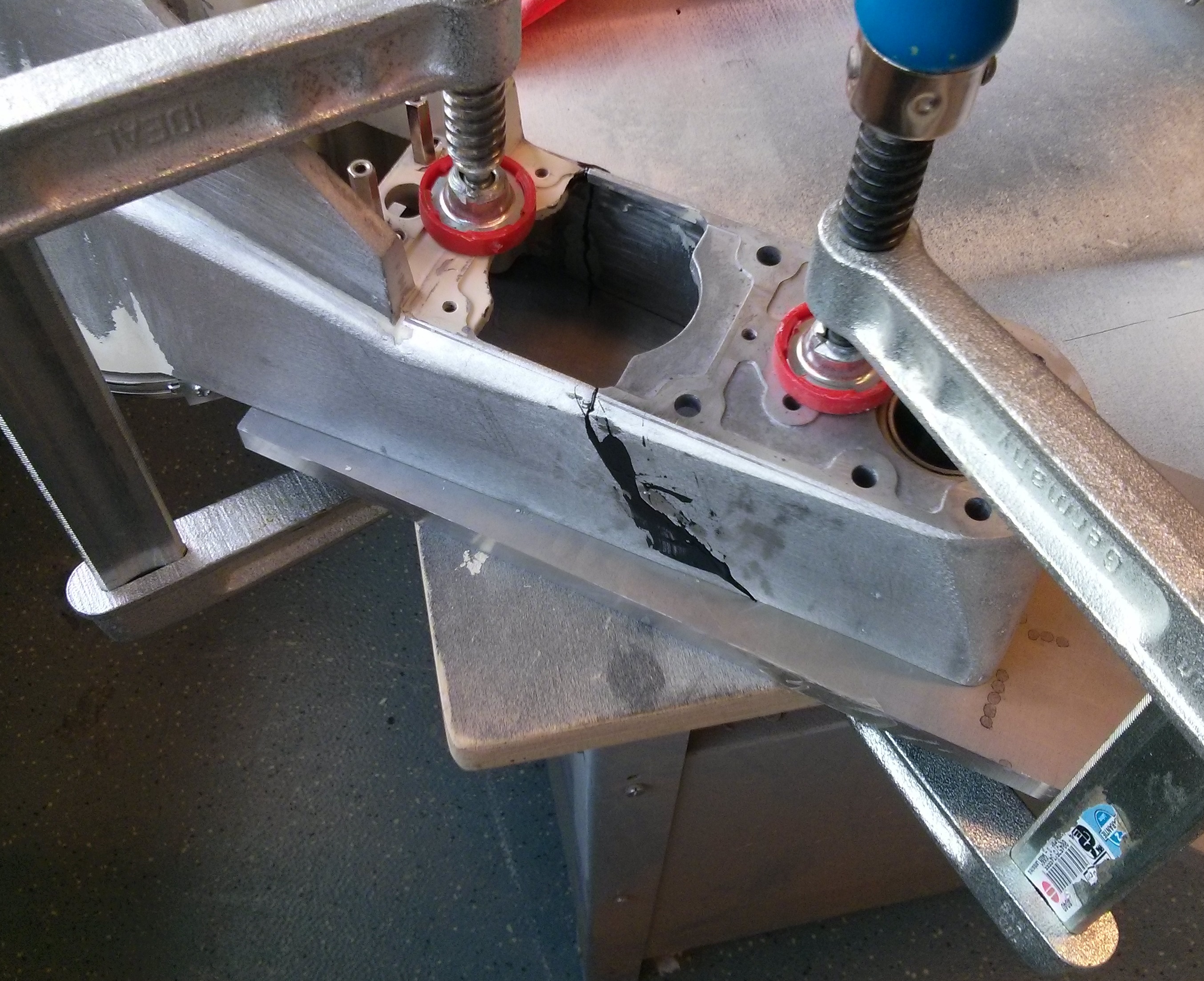
I prepared the parts by grinding away all paint and about 100microns of the aluminium. The last step helps because cast aluminium has different properties on the outer layers compared to the inner bulk material due to the casting process. I also cut some reinforcement plates from 6061 Aluminium. Then I cleaned everything several times with water/soap and acetone. Everything was clamped down on a clean plate and glued together in two steps: First the two broken bits were fixed together. After curing the residual glue was removed by grinding, then the reinforcement plates were glued. To improve the curing process I put a box over it to trap the air inside and heated everyhing which a hot air gun to 80°C. Unfortunately I didnt take that many pictures of the process:
broken B-Arm with mockup reinforcement plate
right side after first glue stop
left side after first glue stop
After that, I did some cosmetics. With a lot of car putty, grinding and even more putty and finally a red finish the part looked like this:
Fixed B-Arm with W-Motor already mounted
That concludes the B-Arm. Fixing the Z-Motor-Plate was basically the same. Here are some more pictures:
glueing the Z-Motor-Mount
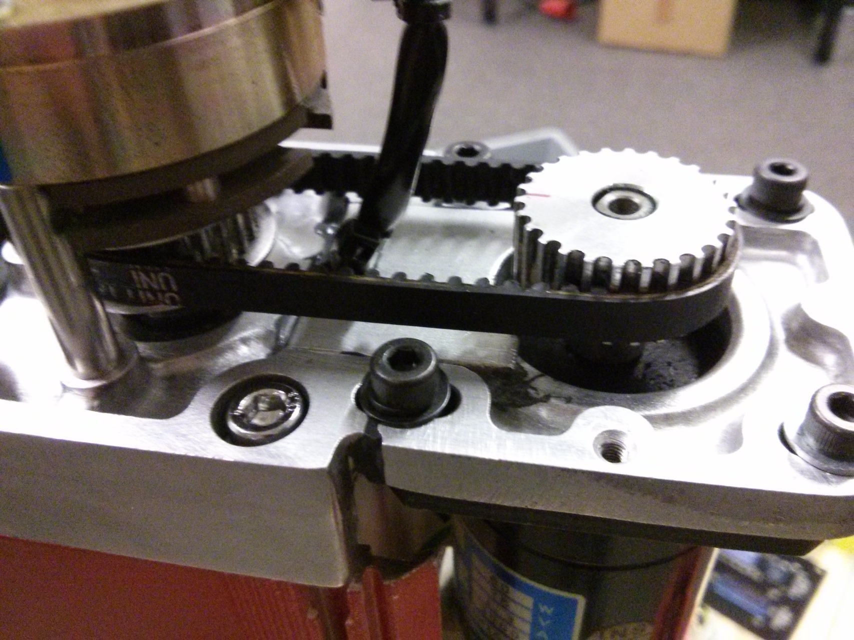
Z-Motor-Mount fixed & assembled
That concludes the repair. I will cover the mechanical and electrical rebuild in a seperate Blogpost.
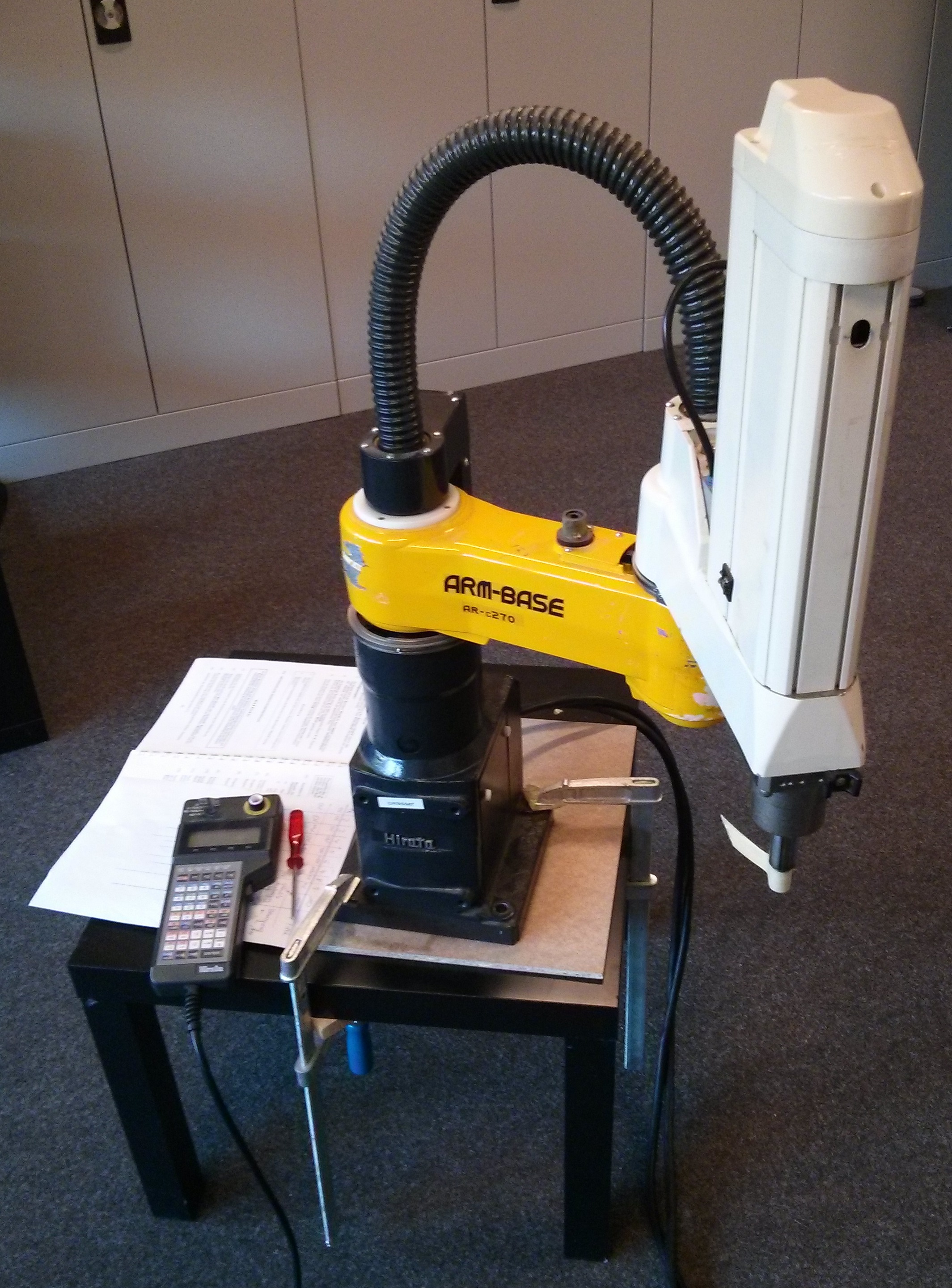
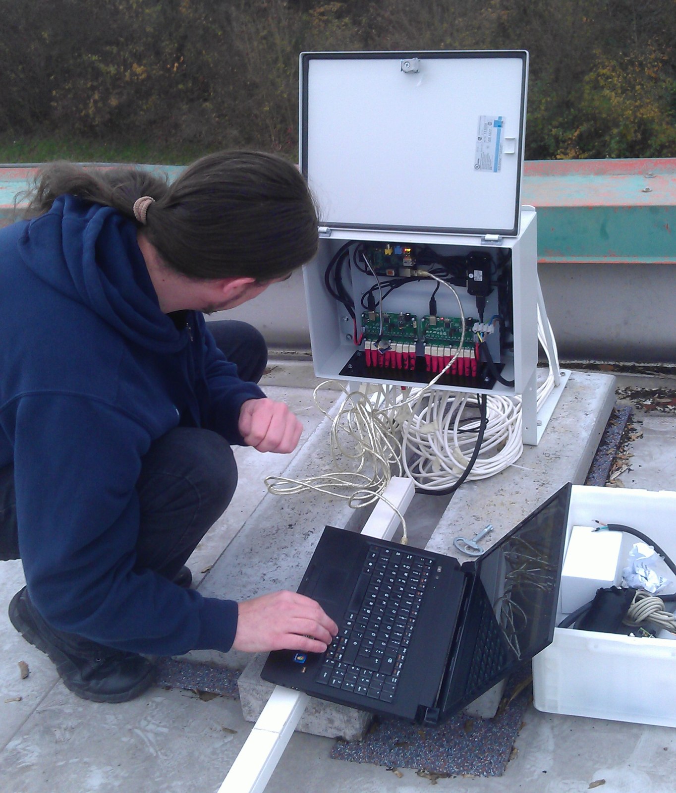
Recently I bought a Scara-Robot from Ebay. Its an older model with an outdated control. Motors, servos and encoders are in working condition. Using the Teach-Pendant I can move the Robot around.
My plan is to retrofit the control using linuxcnc. All IO will be done with a MESA 7i77+5i25 combo. I will try to reuse everything besides the original control.
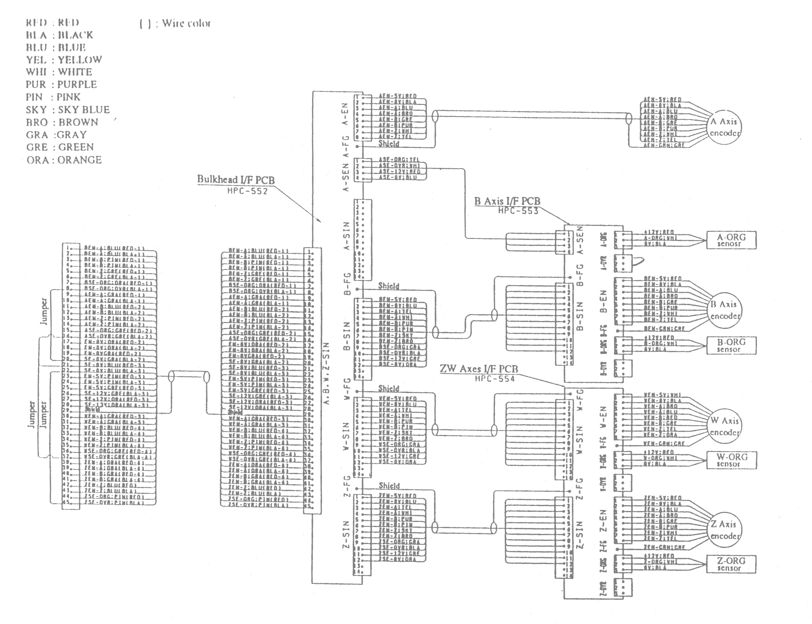
There was quite a lot of documentation included in the Ebay auction, but most of it only covers software. No hints on the pinouts of the servo amp. The company producing the robot still exists, so I gave them a phone-call to request additional docs. I bought the manuals they offered me, but unfortunately they didn’t help at all. So I had to take the thing apart and try to reverse engineer the important parts. My findings so far are all in this 20150422_doku_hac214a.
HPC-53IDI Servo Amplifier
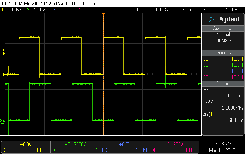
There are some diagramms for the motor- and encoder connections. And yes, the encoders produce a nice A/B-Signal:
Encoder and Limit Switches
Motors and Brake
Encoder pulses
As a next step I will test on of the amps standalone. Hopefully the info extracted so far is okay. Running the amps in velocity mode will make it easy to connect everything to the 7I77.
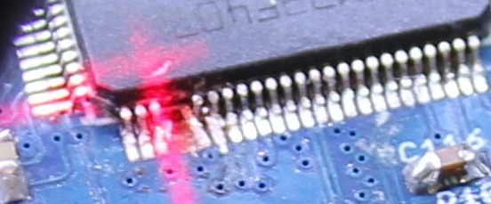
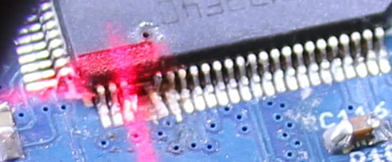
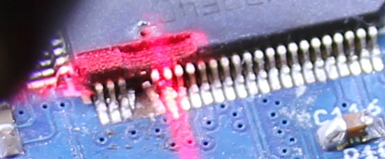
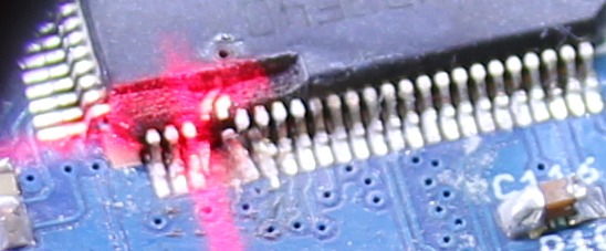
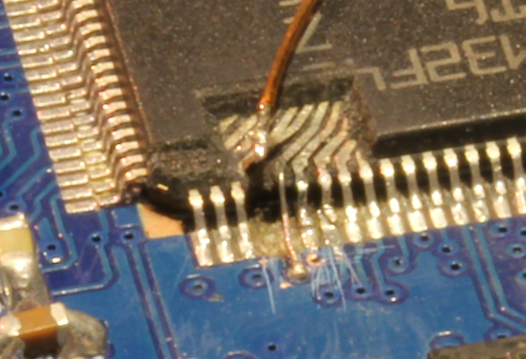
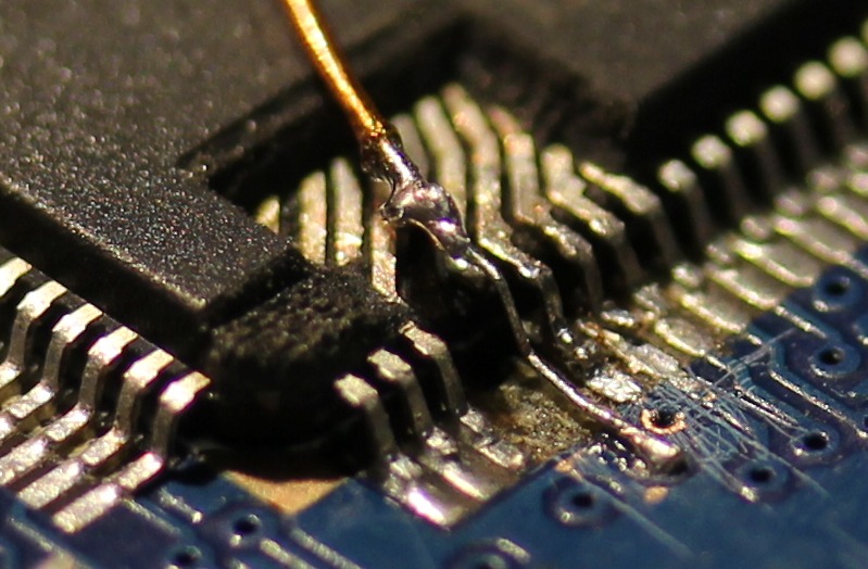
Since a few of the Pads already were delaminated I decided to do a repair instead of soldering in a new CPU. For a repair I would need to get rid of the expoxy mold to directly acces the pins of the leadframe. Initially I was thinking of using a ‘dreml’ tool to remove the exoxy, but watching the Uncaging Microchips talk at 31C3 taught me that using a CO2-Laser will also work.
Those pictures were taken during the laser-removal:
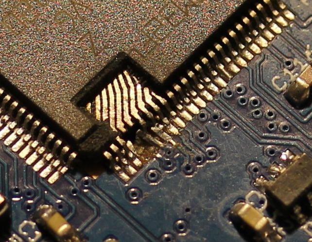
After lasering, all left to do was attach new wires. I did use a microscope for that. For scale, the wire running on top of the CPU has a 0.3mm diameter.
I ran some quick tests with the software to make sure the repair worked. Then a blob of hotmelt was applied to secure and protect the repaired pins:
Backstory: I am also responsible for breaking the pins. I did solder the CPU at 31C3 without proper lighting using borrowed equipment. The temperature on the soldering iron was set to 450°C, I failed to check that. This lead to some major fuckup. Since I wanted to work with the board, the decision was made to simply cut of the broken pins. At the time I didnt need them.
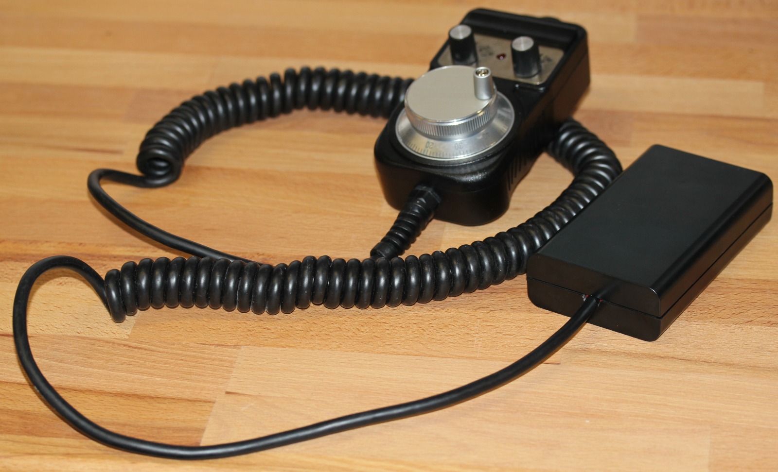
To make jogging easier (doing this with the keyboard sucks) I decided its time to build a remote pendant for my Mill. From ebay I ordered a Device with a MPG (Manual Pulse Generator) and two rotary switches. Its prebuild with a case and cable. Like most china-ware, there was no documentation. But I could open the case to check the wiring and cable-colors.
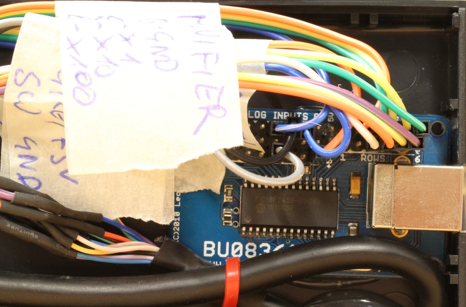
The USB-Interface is a BU0836A device. It allows 8 analog inputs (unused) and 12 switches.
BU0836A USB Interface
LinuxCNC Remote Pendant
To make the MPG work one needs to configure a pair of inputs of the BU0836 for quadrature encoder. Fortunately there is a config utility for linux. The acutual connection was done by soldering female headers to the open cable ends of the pendant (as seen in picture 1). The pinout is as following:
Encoder +5V -> +5V
Encoder GND -> GND
Encoder A -> SW5
Encoder B -> SW6
COMM -> GND
LED- > GND
LED+ -> +5V, with 470R in series
X1 -> SW4
X10 -> SW3
X100 -> SW2
AxisX -> SW12
AxisY -> SW11
AxisZ -> SW10
Axis4 -> SW9
The BU0836 PCB was build into a PVC for protection.
Not only the software-part ist left. To make it work in linuxcnc only a few lines of HAL code are required 🙂
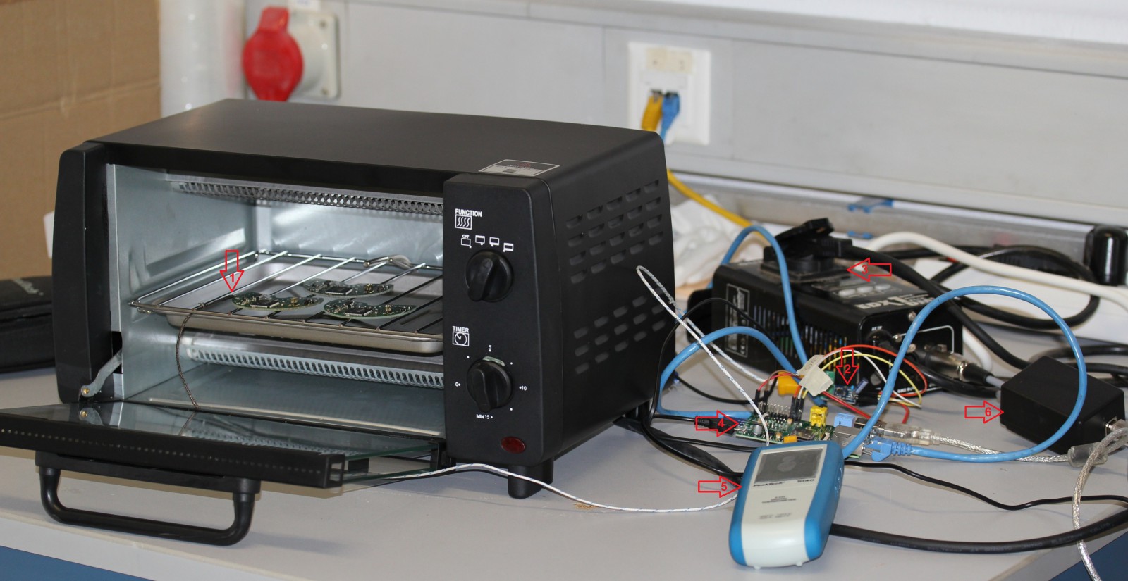
Using a pizza oven for reflow soldering has already been done a million times by hackers/makers all over the world. You can even buy a ready made reflow controllers for such setups. Still, I will present my approach here since it is a little bit different from others I have seen so far.
Most setups use a relay to switch the heating element on/off. Some designs use a SSR and even have elaborate features like zero-crossing-detect. However, I didnt want to mess around with mains voltage. Thats why I decided to use a DMX512-Dimmer do control the heating element. When you think about it, its just another kind of lamp. So why not use a device made to control lamps?
The actual control is done with a Raspberry-Pi. I used a “max6667” Thermocouple amplifier from ebay which is interfaced via SPI. Fortunately there was enought sample code available on the net, I only had to do a litte copy&paste to get it running. I did modify the code to use the py-spidev library. My sourcecode is attached to this post. I also used python to run the PID-Temperature-Loop. Since that code is really ugly I wont publish it now 😀
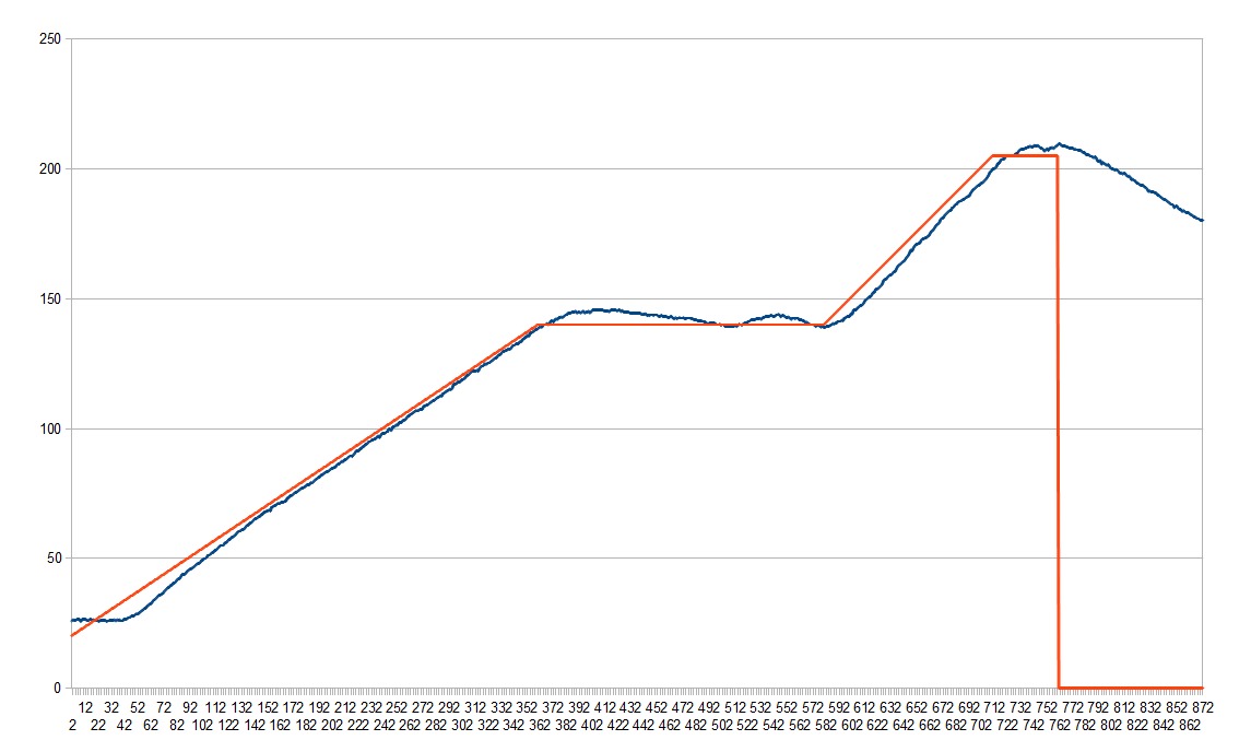
As mentioned above, a PID-Algorithm was used to control the temperature. The Profile is rather slow, but it does work. I might add insulation to the oven to allow faster heating.
Recently I bought a 2-Player Starterdeck for the “My Litte Pony” CCG. One of the aspects of the game is managing you ActionsPoints.
The StarterBox did include some counters/tokens made from thin cartboard, but those are not easy to use. I also tried using dice to keep track of the actionpoints, but thats also not optimal.
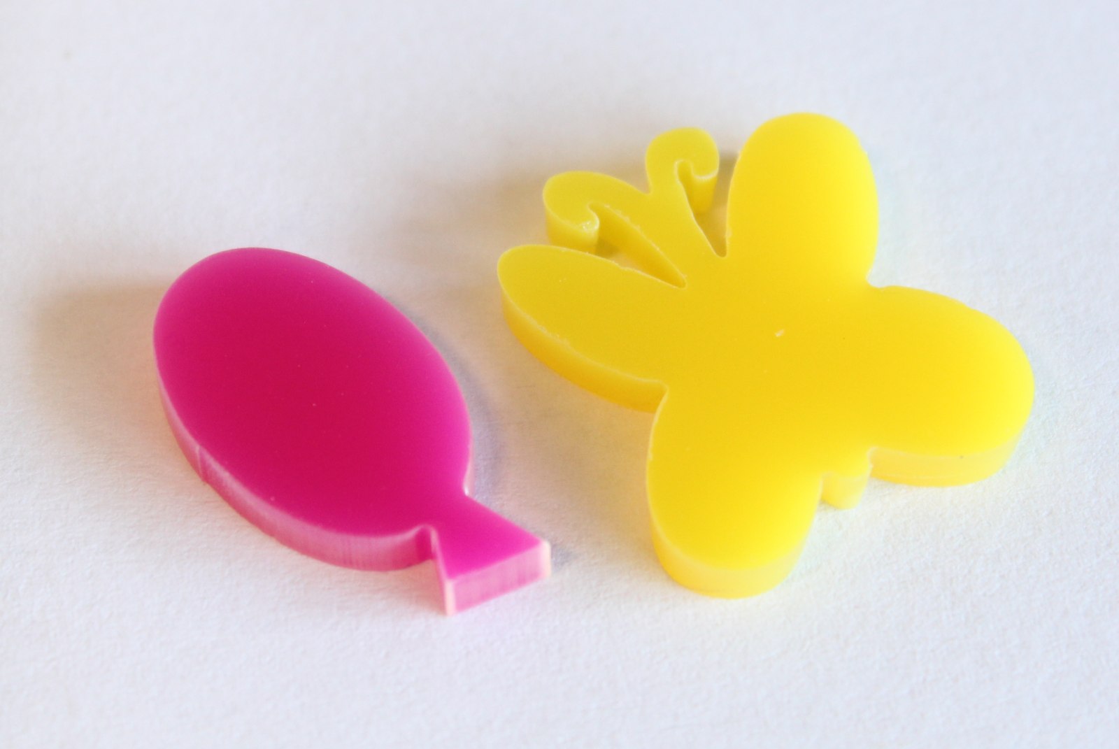
Thats why I decided to create some tokens:
MLP CCG Tokens
MLP CCG Tokens Closeup
The material I used is Perspex (color-codes 2TL2 and 4TL1) in 3mm thickness.
The Design is based on My Little Pony Printable Cutie Marks which can be found on Thingiverse. I did some small modifications. The butterfly had some parts which were to small to lasercut; I enlarged those.
You can download the modified .eps files here: MLP.CCG.Tokens
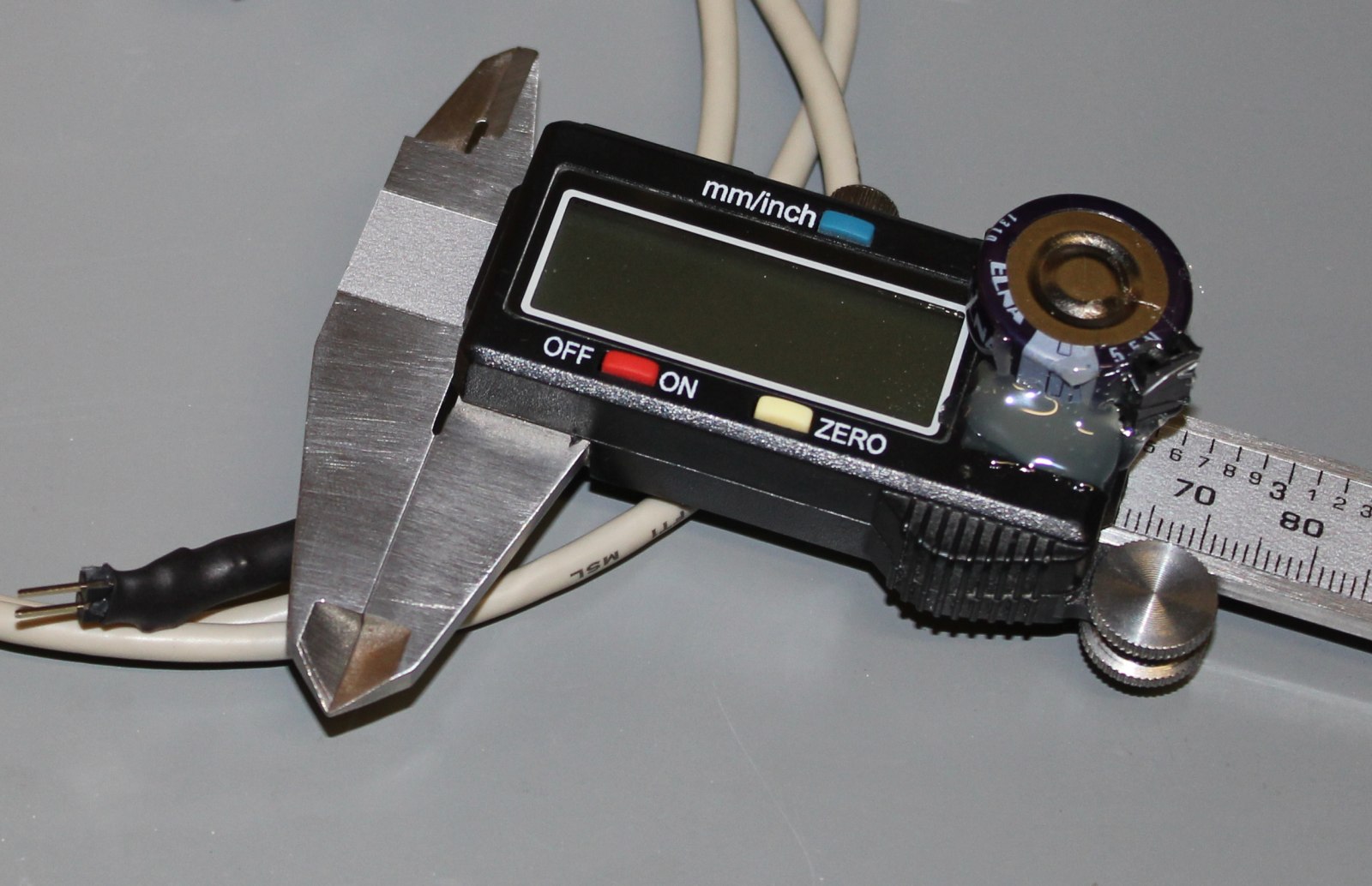
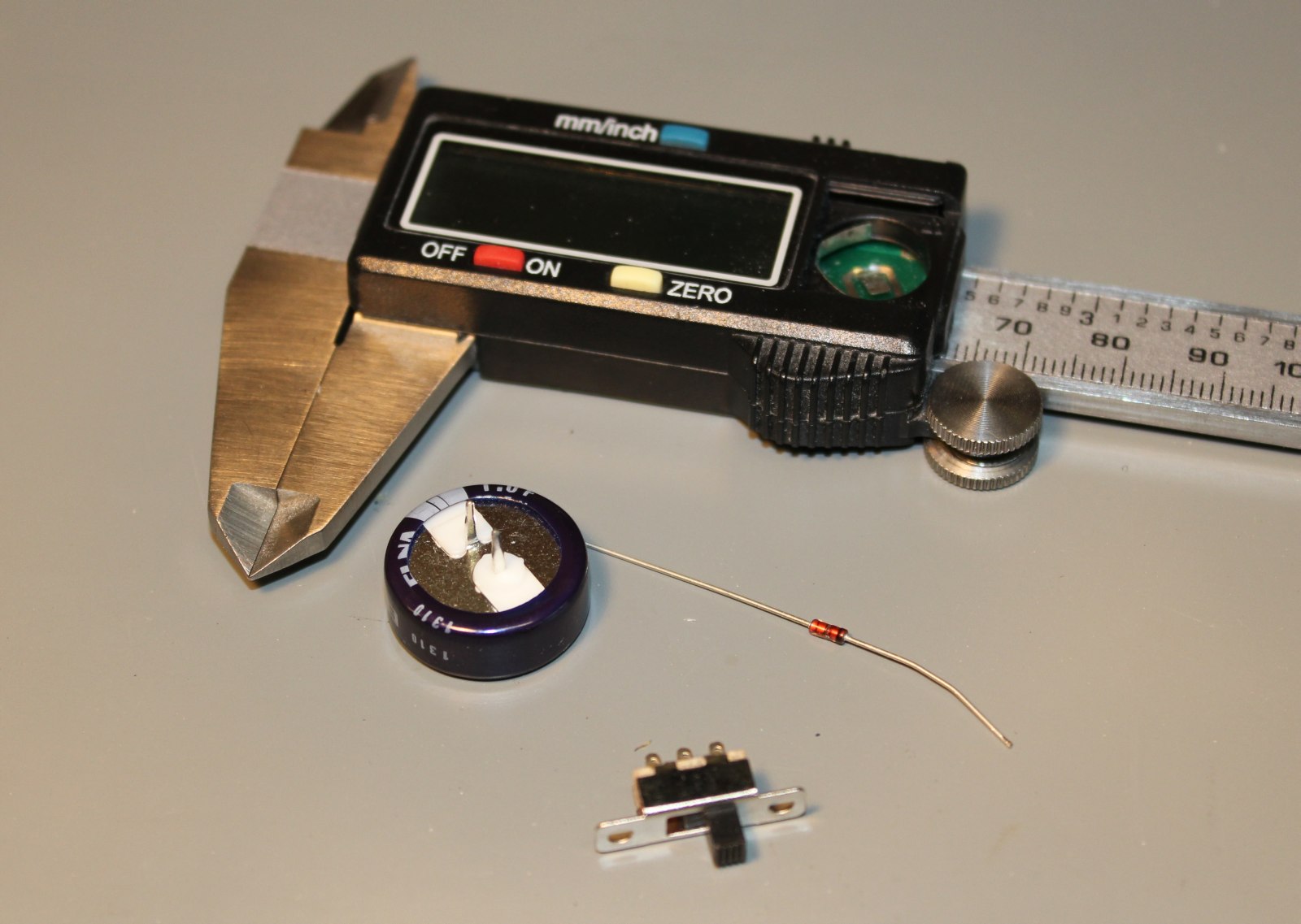
I got the calipers off ebay (<10$) quite a while ago, but they kept draining the battery really fast. After i discovered this blogpost I decided to modify my calipers in a similar way.
The basic idea is the same:
replace the battery with a supercap
build a charging device
The only real difference compared to trevors project is the voltage used. I didnt have a 1.8V LDO around, so i decided to go with 3.3V. An additional SI-Diode in the charging-path drops 0.7Volt, so the actual voltage for a charged cap is 2.6V which seems to be fine for the caliper (i did no long-time test yet). Also, with that diode one cant blow the cap by charging with reverse polarity.
I only used parts you can get from the german distributor Reichelt. The cap is a “SPK 1.0F”, the switch is called ‘T215″.
Parts used
remove plastics to make space for the switch
pre-assembled cap
I did not much testing yet. But the cap kept enough power to work with the caliper even after 80 hours ‘standby’ 🙂
Earlier this year my colleague Rüdiger and me build some LED-Letters and mounted them to the building front. The letters themselfes are made of 20mm Acrylic with buildin RGB-LEDs. A 3mm black Acrylic plate was added on top to cover the LEDs and generate more contrast for daylight conditions.
This is actually me working. A rare picture 😀
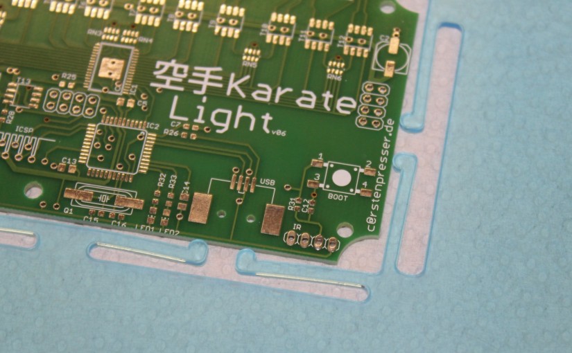
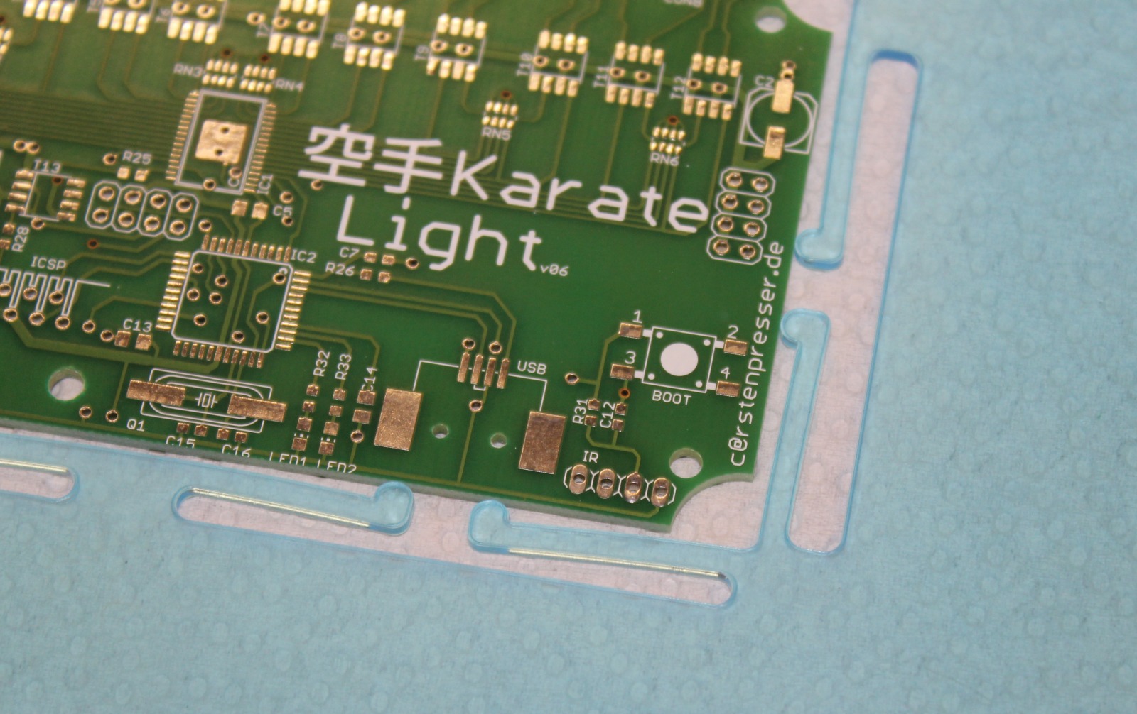
The control is build around the OLA Software. A Raspberry-Pi drives all the components. Two KarateLight devices provide 8 RGB channels each. A USB-Hub (which also poweres the Pi) and a USB-WLAN-Stick make the setup complete. The LEDs are powered by two 320Watt switching-mode PSU. Everyhting fits nicely into a steel cabinet which makes this thing waterproof. In order to organize the cables coming in at the bottom I build two combs which clamp the cables into place.
Since i dont have a cool DMX Application i wrote a few lines of python to generate a simple animation. Basically all it does is calculate a gauss-distribusion which is then shifted from left to right. Its quite simple and not well implemented, but it works: ola.python_fader.
I then use ola_recorder to store a single run of the script into a file. Playback is also done with ola_recorder running inside screen.