Repair Samsung S27C590H LED Backlight

This Samsung 27″ monitor recently stopped working and would not stay on. After power-up, it shows the menu and input-source, but then shuts down again. Interestingly that is the same behavior as described in this reddit post. The only comment in that post says

test the LEDs. if one is bad, the entire system enters shutdown

So lets do that (info on how to open that thing is at the end of this post). I started by looking at the negative side of the LED supply on the mainboard. As you can see, I marked of the test-points (LED2) red because that corresponds to the LED stripe that does not work properly. The voltages on the LED test points should be close to zero, the working ones had about 0.8V. The channel with issues was about 18V, but quickly dropped since the controller did detect this and restart the system. The positive supply of the LEDs has 68V. That matches the information from the reddit post.

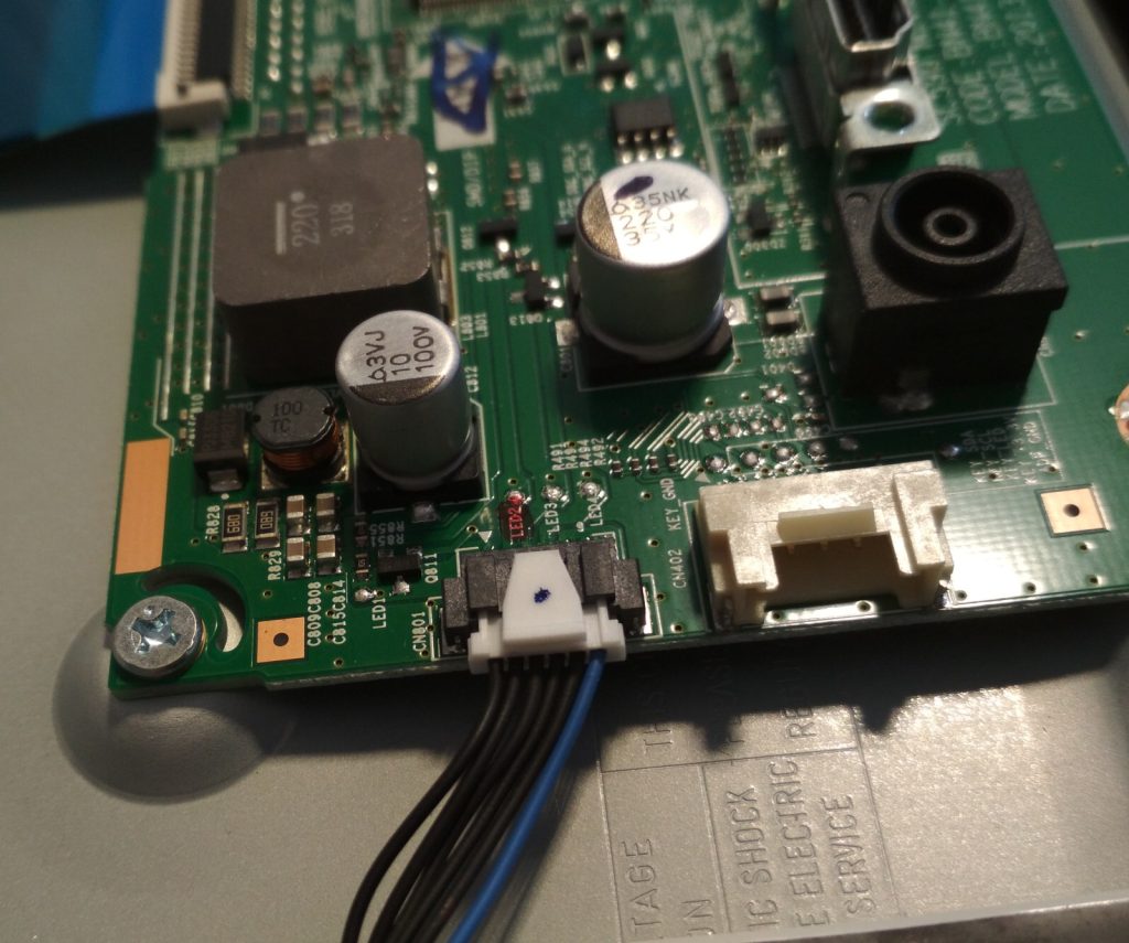
Controller PCB, a white connector with 6 conductors.
A beefy inductor and some caps are visible.

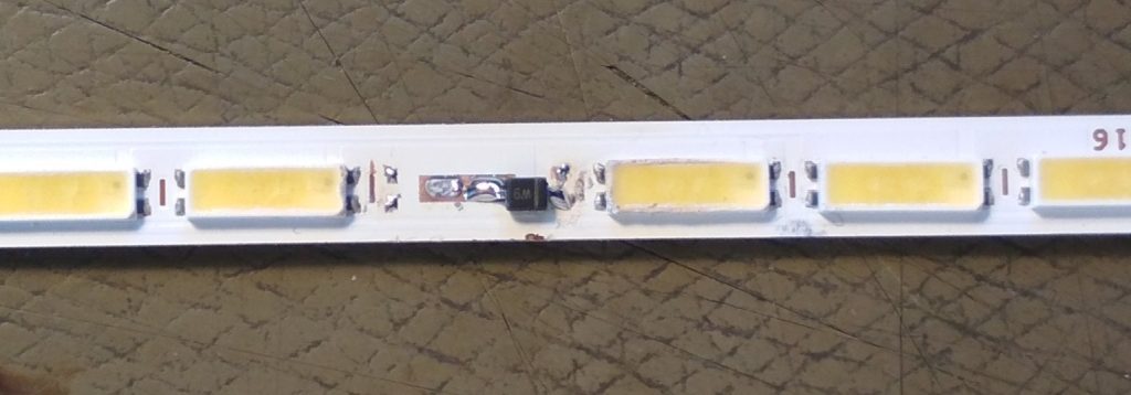
By carefully removing the wires from the LED connector that corresponds to the broken channel I could verify that the rest of the screen is working properly. It stayed on and displayed a picture. Albeit, there was a huge dark streak where part of the backlight is missing. That means we need to remove the backlight and fix it. After some more disassembly, the LEDs could be removed. With a multimeter in diode test mode one of the LEDs was found to be non working. Since I don’t have the correct LED or even something similar (those LEDs seem to have a Vf of 5.5V), the solution was to solder in a zener diode with 5.6V. Fortunately my parts drawer has a set of various zeners.

A thin PCB with LEDs
one LED has been replaced with a smol zener diode.
One LED module replaced with a zener diode.

Now the screen just needs to be assembled again.

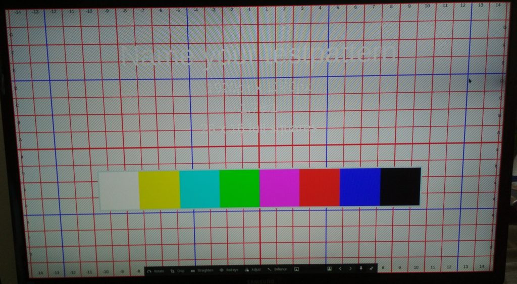
A test-image
on the right side, close to the cursor, there is a dark spot.
A slight dark spot/sliver on the right side

More disassembly pics

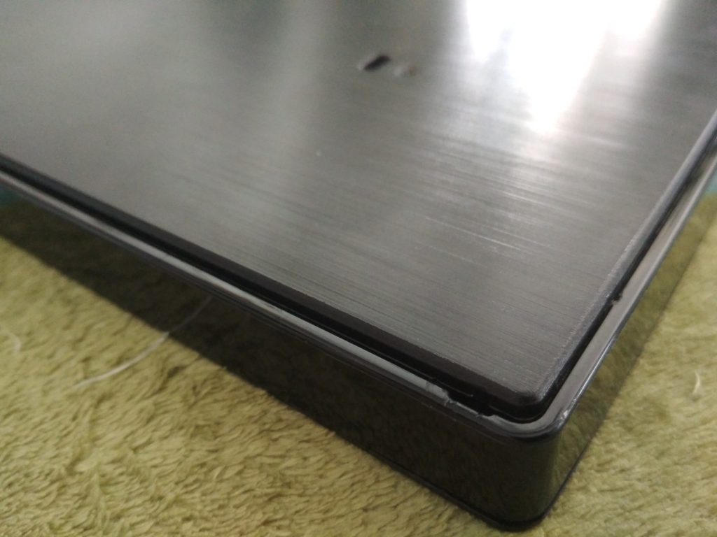
The corner where one can start to remove the back panel.
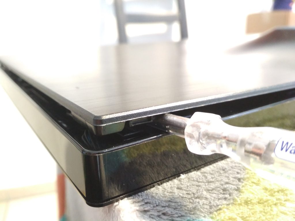
Closeup of the plastic snap thingies of the back panel
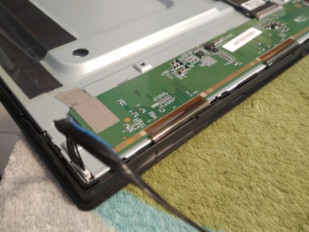
Open screen, display-driver boards at the bottom. LED-Cable on the left. The front bezel is still attached.
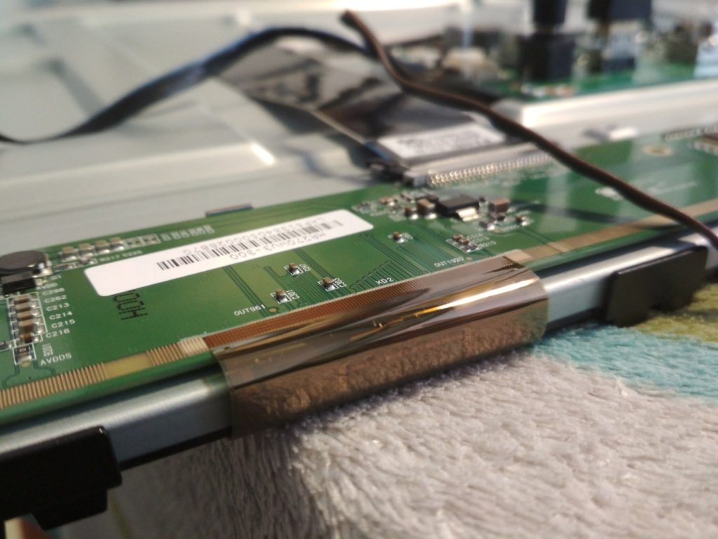
screen with front bezel removed. The flex cable connecting to the glass substrate is visible.
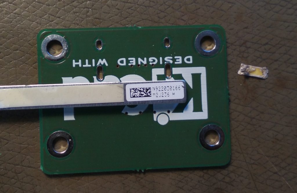
Sticker that identifies the backlight LED strip

Fixing the DEC VT220 flyback transformer

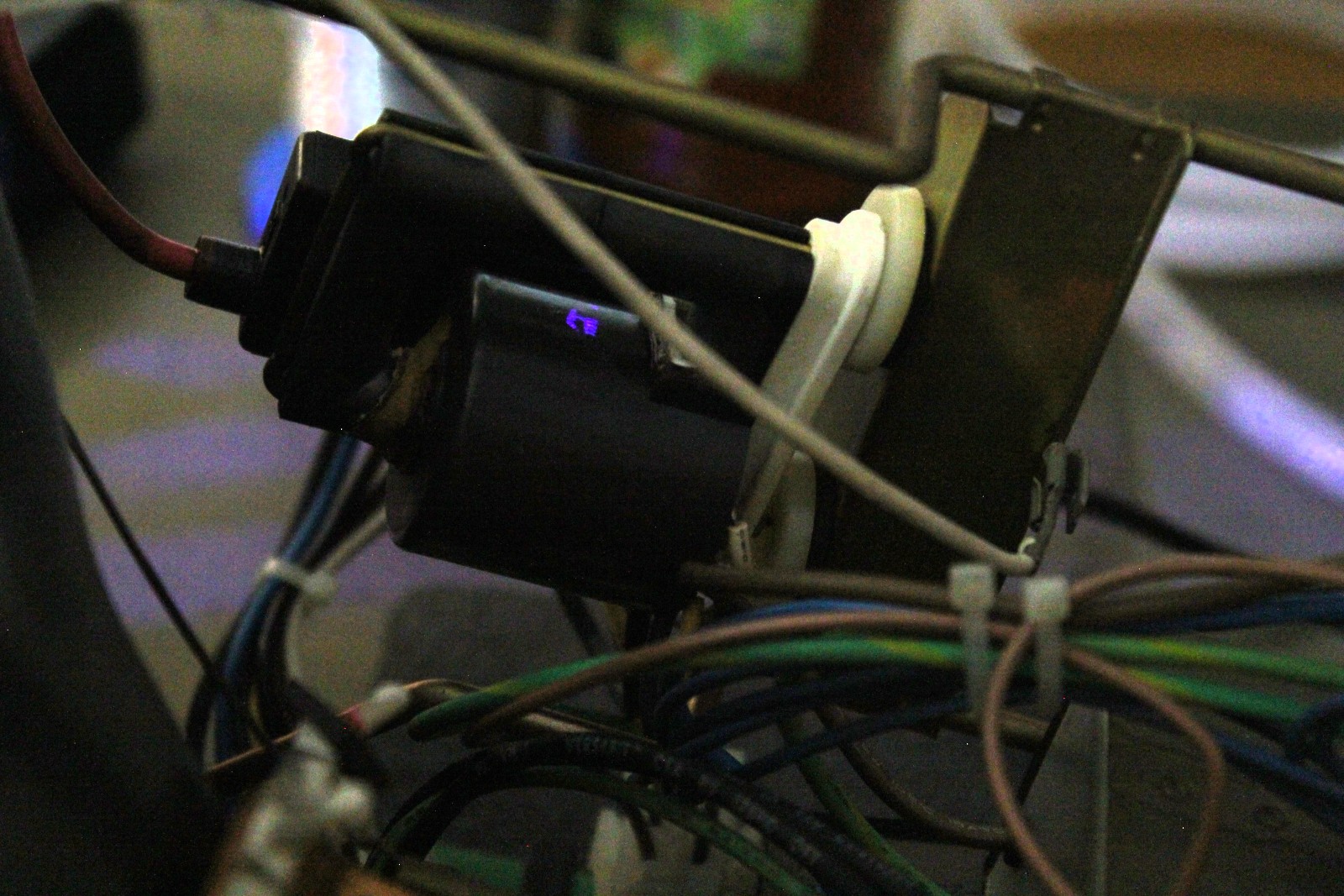
Unfortunately my VT220 did not work well. The flyback transformator is leaky. It can be heard and smelled (the ozone generated by the arc). In a low light environment the arc is also visible (blue-violet spot in the center of the picture).

flyback transformer with visible arc

Most resources on the internet suggest to just get a replacement. Some comments even say it is dangerous to try a repair, but fail to mention exactly why. Getting a replacement is pretty hard for such an old device. I checked the google-search, ebay and hr diemen. But I was not successful.

The I came upon this post on reddit/imgur: https://imgur.com/a/uEAlQ3j which tackles the same issue.

I choose to do something similar. Use epoxy to re-seal the transformer. But instead of brushing it on I wanted to add a thicker layer.

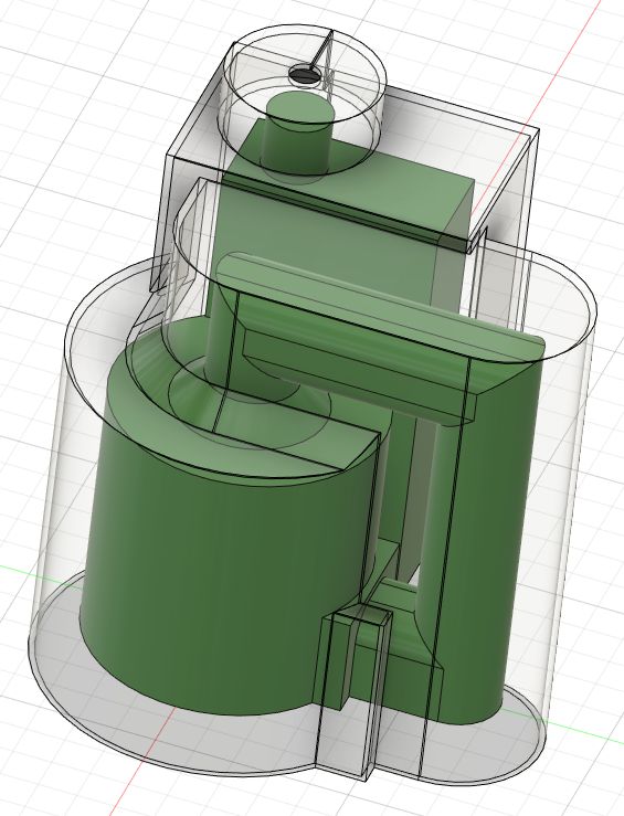
The first step was to make a rough 3D-Model of the existing transformer. Then offset it by 5mm outside to create a mold. That mold was printed in PLA.

3D-Model of the transformer with mold

I did not take any pictures during the casting process. I used hot-glue to fix the flyback in the mold so it does not move while casting. The epoxy used was E45GB with some green pigment mixed in. The volume needed was extracted from the 3D-Model of the mold and the transformer. Make sure to factor in the density of the epoxy, I did not and had to mix a second smaller batch

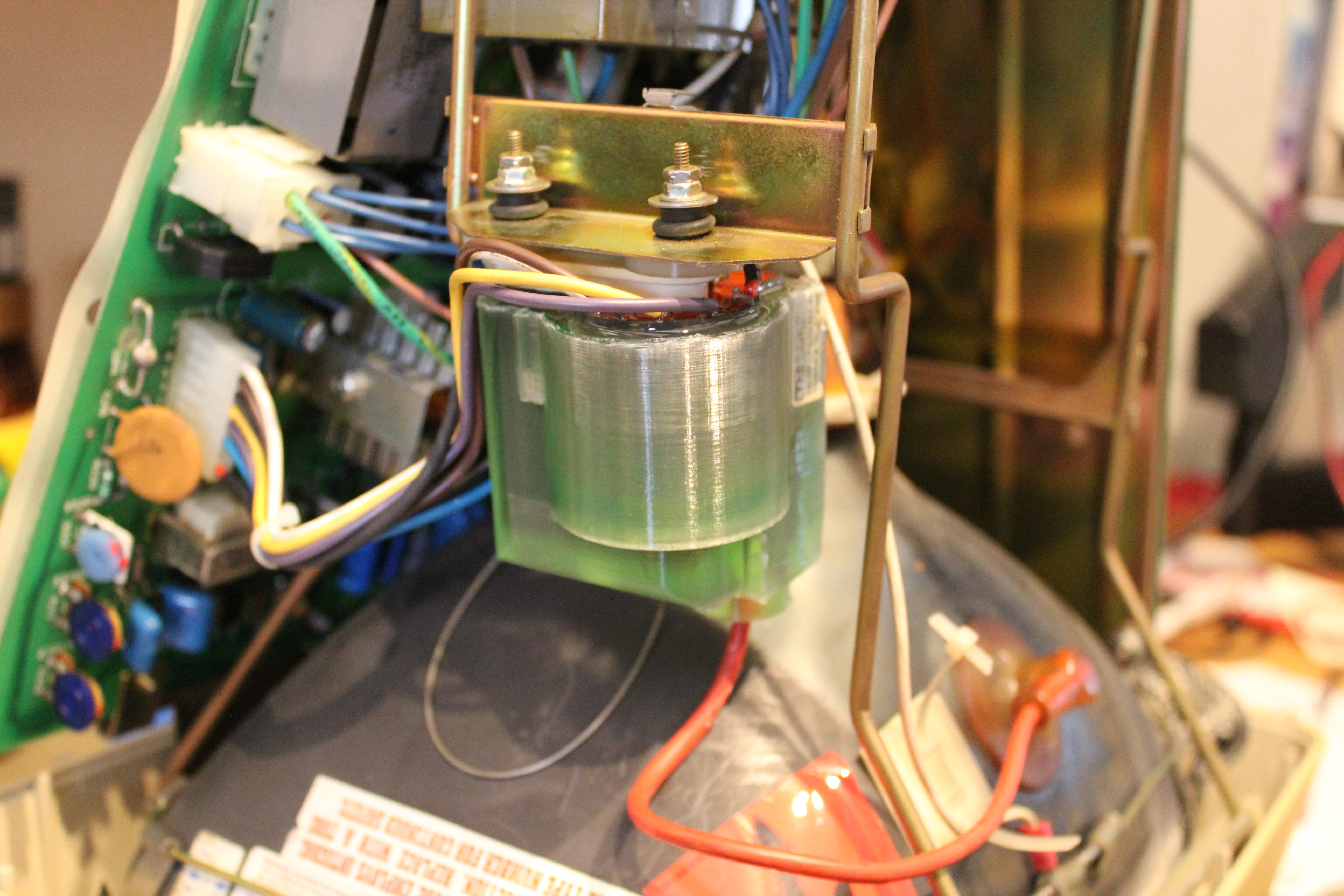
newly molded flyback mounted in the vt220

As you can see above I did not remove the mold. Its fixed to the epoxy. Next time I will use a release agent.

But did it work? I would say yes. There is no more arcing and I cant smell any ozone anymore. It also more silent, but the typical 15kHz(?) noise is still present.


Fixing “108.08” error on a lexmark C546dtn printer

The printer that I have been using for quite some time recently stopped working. The display indicated that the error is “108.08”.

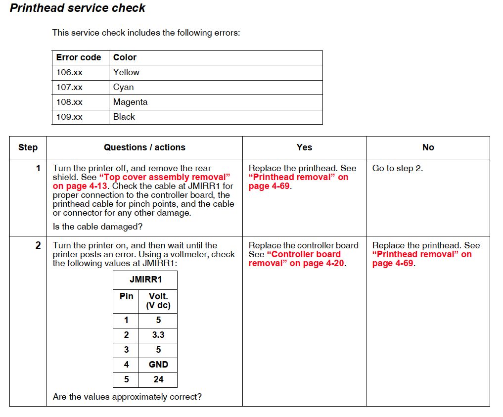
A quick search got me the service-manual for this printer. This is a really great document. It has all the instructions needed to diagnose and fix an error. Detailed disassemly instructions can also be found.

Service instructions for the 108.xx error

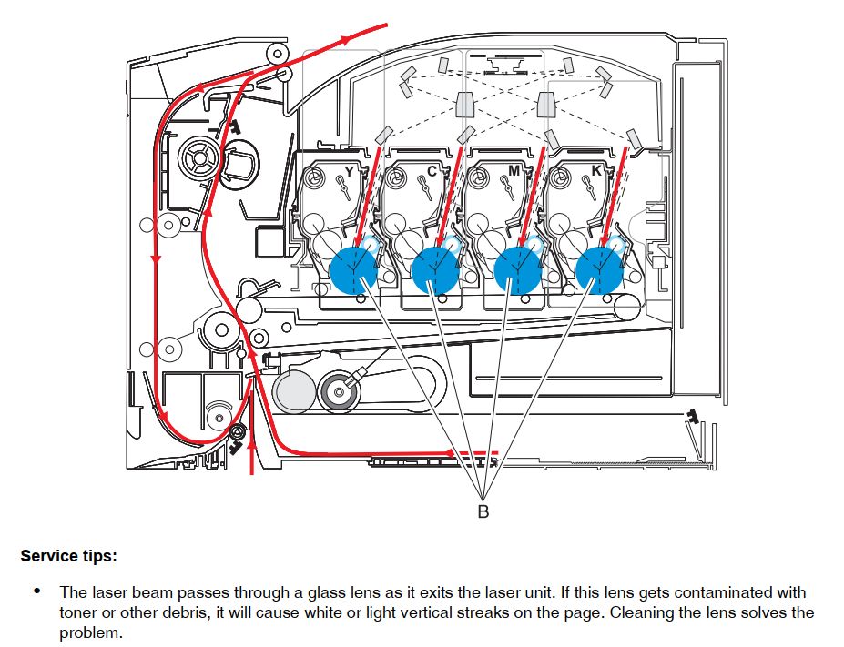
I did all of that, but instead of replacing the printhead I just cleaned it. Over the time dust does accumulate on the windows where the laser light exits the printhead. After disassembly I could clearly see that the windows were cloudy; colorful toner could als be spoted on the windows. My solution was to use a kimtech wipe without any water/solvent to clean the lenses.

The manual actually says to clean those windows, but its on another page/section not directly related to that error.

Illustration how paper and light are routed through the printer

Scara Robot Repair – Learning stuff the hard way

Turns out the drives of my Scara Robot are not velocity-mode drives but torque-mode drives instead. Setting the drive input to a constant voltage results in constant accelleration. I learned this the hard way by crashing the robot :-/

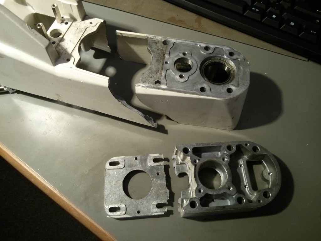
Even though I had it fixed on an Europalette it managed to fall on its side. Second lesson learned: even ‘small’ a 200W drive can turn the whole thing in a fraction of a second. Hitting the floor broke some pieces. But see for yourself:

B-Arm and Z-Motor-Plate destruction

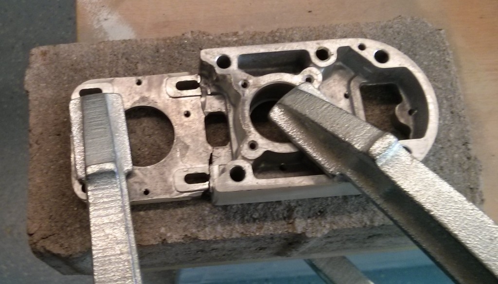
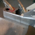
Those parts are both made out of cast aluminium. I do lack the equipment and skill to weld, so I asked a Friend of mine to do it. However, even with his long time experience he wasn’t able to fix the parts together. At first I got desperate and tried hard-soldering the Z-Motor-Mount. But even using two torches I wasnt able to get the part hot enough to accept the solder.

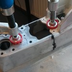
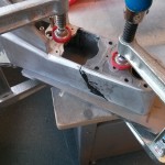
Z-Motor-Plate fixed with clamps ready to solder

As a last resort I deceided to glue the parts. Fortunately my sister works as a postdoc and is an expert for aluminium epoxy bonds. She did some rought calculations for me and helped select the correct adhesive: 3M Scotch-Weld DP490.

I prepared the parts by grinding away all paint and about 100microns of the aluminium. The last step helps because cast aluminium has different properties on the outer layers compared to the inner bulk material due to the casting process. I also cut some reinforcement plates from 6061 Aluminium. Then I cleaned everything several times with water/soap and acetone. Everything was clamped down on a clean plate and glued together in two steps: First the two broken bits were fixed together. After curing the residual glue was removed by grinding, then the reinforcement plates were glued. To improve the curing process I put a box over it to trap the air inside and heated everyhing which a hot air gun to 80°C. Unfortunately I didnt take that many pictures of the process:

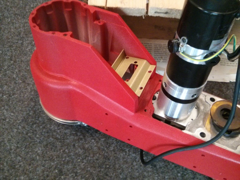
After that, I did some cosmetics. With a lot of car putty, grinding and even more putty and finally a red finish the part looked like this:

Fixed B-Arm with W-Motor already mounted


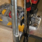
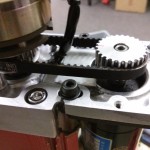
That concludes the B-Arm. Fixing the Z-Motor-Plate was basically the same. Here are some more pictures:

That concludes the repair. I will cover the mechanical and electrical rebuild in a seperate Blogpost.